 |
 |
Adding a Water Level Gauge to
the Saddle Tank
| This modification is one of those that may not be really necessary but which makes the drivers life much simpler because you can see at a glance how much water remains in the saddle tank without having to get off and lift the tank cover. What made it even better was that I had enough material in my scrap box to make it, although the main plate did have to be made from two lengths of brass flat silver soldered together. The 8 mm diameter glass tube was purchased from R A Barker (see the links page) at the same time as the whistle. | |
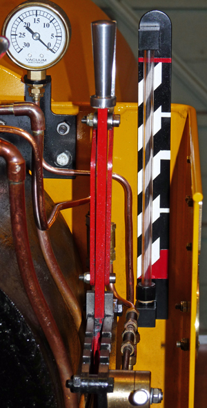 There
is nothing very difficult in building this water gauge other than
connecting it into the existing saddle tank plumbing and all the parts
can be made on a small lathe or using hand tools. The glass
sight
tube is mounted using an 'O' ring at either end; the bottom ring being
compressed by the gland nut while the top ring simply fits in a groove
inside the detachable top block. To stop sloshing of
the
water in the saddle tank from affecting the level in the gauge the
bulkhead adaptor fitting at the bottom of the gauge that bolts through
the
cab was only drilled with a 1 mm diameter hole for the water to pass
through. The fun part came in calibrating the gauge because
the
scale is non linear due to the curving shape of the saddle tank, so an
hour or two was spent playing with water and measuring jugs.
To
save any of you building the gauge having to do the same I have
included the calibration figures below. They are all
referenced
to the top edge of the beading that runs around the cab sides. There
is nothing very difficult in building this water gauge other than
connecting it into the existing saddle tank plumbing and all the parts
can be made on a small lathe or using hand tools. The glass
sight
tube is mounted using an 'O' ring at either end; the bottom ring being
compressed by the gland nut while the top ring simply fits in a groove
inside the detachable top block. To stop sloshing of
the
water in the saddle tank from affecting the level in the gauge the
bulkhead adaptor fitting at the bottom of the gauge that bolts through
the
cab was only drilled with a 1 mm diameter hole for the water to pass
through. The fun part came in calibrating the gauge because
the
scale is non linear due to the curving shape of the saddle tank, so an
hour or two was spent playing with water and measuring jugs.
To
save any of you building the gauge having to do the same I have
included the calibration figures below. They are all
referenced
to the top edge of the beading that runs around the cab sides.Full = + 36 mm 3/4 = -- 38 mm 1/2 = -- 84 mm Empty = --141 mm The connection to the saddle tank was made using normal copper tube and cones, but the difficult bit was setting the connector on the saddle tank balance pipe in exactly the right 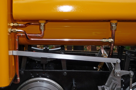 place. The position on the balance pipe was marked with the
pipe
still fitted to the loco, and then the pipe was removed and placed flat
on the pillar drill table. A 1/16 inch was then drilled in
the
correct position. The pipe union was made with the its 1/8
inch
bore not drilled all the way through, but drilled through with a 1/16
inch hole. A short length of 1/16 inch brass rod was then put
through the holes to locate the union exactly on the balance pipe while
the joint was silver soldered, after which the union bore was drilled
through into the balance pipe using the 1/8 inch drill. If
you do
this, make sure that you remove all the swarf from inside the pipes
before refitting.
place. The position on the balance pipe was marked with the
pipe
still fitted to the loco, and then the pipe was removed and placed flat
on the pillar drill table. A 1/16 inch was then drilled in
the
correct position. The pipe union was made with the its 1/8
inch
bore not drilled all the way through, but drilled through with a 1/16
inch hole. A short length of 1/16 inch brass rod was then put
through the holes to locate the union exactly on the balance pipe while
the joint was silver soldered, after which the union bore was drilled
through into the balance pipe using the 1/8 inch drill. If
you do
this, make sure that you remove all the swarf from inside the pipes
before refitting.For those of you who have CAD on your computer you can download my CAD drawing in .dwg format by right clicking on the link below and then saving the file on your computer. Please note that the drawing is predominantly metric and is drawn full size. Gentoo's Journals provides the drawing "for guidance only" and does not guarantee its accuracy or completeness. Right click here for the CAD .dwg file. |
|