 |
 |
The Injector Clack Valves
| As mentioned in the problems pages the injector clack valves fitted to the Stafford work completely satisfactorily under normal circumstances (although I did see two other Stafford's exhibit the same failure at a Stafford Owners Rally). This page explains how I made an alternative to the conventional ball bearing clack valve as an experiment to see if I could overcome my problems. | |
 After
almost 18 months of operating my Stafford with injector clack valves
that were prone to sticking open a fellow club member suggested that I
should try using an O Ring clack valve to see if they would behave any
differently. Unfortunately we could not find any commercially
available O Ring clack valves of a suitable size for the Stafford so I
had to design my own. The main component of the O Ring clack
valve
is obviously the O Ring which has to withstand the boiler water temperature
of 172 degrees
Centigrade at 120 psi. Small Viton O Rings are quite easily
available and can operate at temperatures up to 200 degrees
Centigrade so they became my preferred option. After
almost 18 months of operating my Stafford with injector clack valves
that were prone to sticking open a fellow club member suggested that I
should try using an O Ring clack valve to see if they would behave any
differently. Unfortunately we could not find any commercially
available O Ring clack valves of a suitable size for the Stafford so I
had to design my own. The main component of the O Ring clack
valve
is obviously the O Ring which has to withstand the boiler water temperature
of 172 degrees
Centigrade at 120 psi. Small Viton O Rings are quite easily
available and can operate at temperatures up to 200 degrees
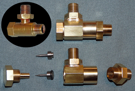
Centigrade so they became my preferred option. The photo shows a completed O Ring clack valve with an original Stafford ball bearing clack valve inset for size comparison. The component parts of the O Ring clack valve are also shown in the photo with a "shuttle" shown in its "as machined" state and after fitting with its O Ring. Ideally the clack valves should be manufactured using gunmetal or phosphor bronze and stainless steel for the shuttle, but to initially test the valves I used the cheaper option of brass for the main components. The loco has now covered over 150 miles with these valves fitted and they have performed perfectly, always closing completely no matter what has happened with the injectors. Why my original ball valves would not operate correctly is a mystery, but these valves have resolved my problem and have definitely become a permanent feature of my Stafford. Their only disadvantage is that the O Ring has to be replaced after about 30 hours "in steam" as it starts to leak when there is no boiler pressure (e.g. before steam is raised). |
|