 |
 |
Essential alterations needed
when fitting a cab
| As soon as I
decided to try and fit a cab
to my Stafford it was obvious that the pressure and vacuum gauges
would need to be relocated so that they would remain visible to the
driver and that the safety valve outlet pipe would require extending to
clear
the cab roof. As these alterations were critical to enable
the
cab to be fitted I initially made a cardboard mock-up of the cab and
positioned it onto the Stafford. This cab mock-up determined
where
the front of the cab had to end in order to fit behind the proposed
extension to the safety valve pipe. By sitting on the driving
truck I was able to determine were the pressure and vacuum gauges would
still be visible, noting that the visibility also depended on the
height of the cab roof and how far backwards it extended.
After a
lot of trial and error with the cardboard I decided that the cab roof
would be about 2 inches (50mm) higher than I would really have liked. |
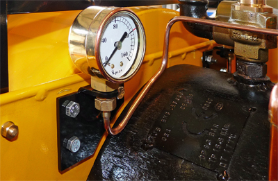 The
boiler pressure gauge was relocated to the left hand side of the cab
and mounted on a new bracket as seen in the photo. The
section of
the bracket that the pressure gauge bolts into was not bent, but was
welded onto the vertical section as I find that method of fabrication
to be quicker and more accurate than trying to bend steel plate. The
boiler pressure gauge was relocated to the left hand side of the cab
and mounted on a new bracket as seen in the photo. The
section of
the bracket that the pressure gauge bolts into was not bent, but was
welded onto the vertical section as I find that method of fabrication
to be quicker and more accurate than trying to bend steel plate.Thankfully the Stafford cab side plate already has the required mounting holes drilled into it (probably because it is a true mirror image of the right hand cab side) so all that is required is a short nut plate tapped M6 to line up with the top two bolts. The bottom bolt is originally used to support the saddle tank so it needs to be replaced with a longer version. The vacuum gauge was mounted using a "mirror image" bracket on the right hand side of the cab and new copper pipes to connect the gauges to their respective "feeds" were also fabricated to fit. |
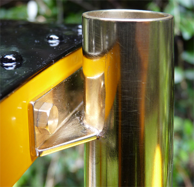 With
a cab roof fitted the safety valve outlet pipe obviously had to be
extended so that it ended up above the roof level, so this meant either
passing it through a hole in the cab roof or starting the roof behind
the safety valve pipe. As can be seen in the photo I chose
the
latter option, partly because it was easier but also because the
proportions of the finished cab looked better. Thankfully on
my
Stafford the safety valve system was aligned exactly along the locos
centre line, but on at least one other Stafford that I have seen the
safety valve outlet is at about 45 degrees to the locos centre line.
This would result in an odd looking safety valve system if
you
didn't want to try rotating the entire safety valve assembly back to
the loco's centre line. With
a cab roof fitted the safety valve outlet pipe obviously had to be
extended so that it ended up above the roof level, so this meant either
passing it through a hole in the cab roof or starting the roof behind
the safety valve pipe. As can be seen in the photo I chose
the
latter option, partly because it was easier but also because the
proportions of the finished cab looked better. Thankfully on
my
Stafford the safety valve system was aligned exactly along the locos
centre line, but on at least one other Stafford that I have seen the
safety valve outlet is at about 45 degrees to the locos centre line.
This would result in an odd looking safety valve system if
you
didn't want to try rotating the entire safety valve assembly back to
the loco's centre line.The safety valve extension was simply made from a length of brass tube that slid over the existing safety valve outlet pipe. The mounting bracket was silver soldered to the top and bolts to the cab using 4 BA brass bolts so that it can easily be removed when cleaning and polishing the loco. |