 |
 |
 |
Footplate Extension
In order to be
able to fit a cab assembly
to the Stafford that appeared to allow space on the footplate for a
driver it was necessary to extend the footplate about 2" (50mm) beyond
the original buffer beam. This extension should have been
easy to
make from a length of mild steel angle (even allowing for the fact that
it had to fit around the dumb buffers) but only after it was cut,
welded and finished did I discover that the loco's rear buffer beam
wasn't straight. As a  result
the first footplate extension I made ended up in the scrap bin and I
had to make a second one. Quite why the rear buffer beam is
not
straight is a bit of a mystery, but suffice to say that it is perfectly
symmetrical with both outer ends 2mm closer to the front of the loco
than the truly straight centre section between the longitudinal frames.
The photo here quite clearly shows the gap between the ruler and the
red buffer beam widening towards the right of the photo. The
other manufacturing problem was getting the fixing holes in the
correct place to match the existing buffer beam mounting bolts.
An email to Station Road Steam very quickly resulted in a set
of
dimensions with the caveat that I should check the positions on my
Stafford "just in case they weren't in accordance with the dimensions
supplied in the email". Measure twice and cut once is a well
known engineering adage, and in this case it was critical as the holes
I needed to use were not where the email suggested.
Thankfully I
did manage to get the holes to line up satisfactorily on that second
attempt at making the footplate extension. result
the first footplate extension I made ended up in the scrap bin and I
had to make a second one. Quite why the rear buffer beam is
not
straight is a bit of a mystery, but suffice to say that it is perfectly
symmetrical with both outer ends 2mm closer to the front of the loco
than the truly straight centre section between the longitudinal frames.
The photo here quite clearly shows the gap between the ruler and the
red buffer beam widening towards the right of the photo. The
other manufacturing problem was getting the fixing holes in the
correct place to match the existing buffer beam mounting bolts.
An email to Station Road Steam very quickly resulted in a set
of
dimensions with the caveat that I should check the positions on my
Stafford "just in case they weren't in accordance with the dimensions
supplied in the email". Measure twice and cut once is a well
known engineering adage, and in this case it was critical as the holes
I needed to use were not where the email suggested.
Thankfully I
did manage to get the holes to line up satisfactorily on that second
attempt at making the footplate extension.Note: Stafford's built in the production batches after mine have a welded chassis and the footplate actually overlaps the rear buffer beam. As a result of this design change anyone wishing to make a similar modification to their Stafford will probably have to use a slightly different design for a footplate extension. |
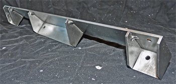
 This
photo shows the second footplate extension ready for painting.
The main footplate, cut from 1/8" (3mm) mild steel sheet, is
shaped to
match the bends in the buffer beam and all of the other parts of the
assembly have been cut from sheet and welded into place. This
took quite a lot of weld dressing to end up with pristine flat faces,
and as it was all done by hand using files followed by various grades
of wet & dry paper it took the best part of a day to make (as
well
as ending up with sore hands from using files for almost 7 hours). This
photo shows the second footplate extension ready for painting.
The main footplate, cut from 1/8" (3mm) mild steel sheet, is
shaped to
match the bends in the buffer beam and all of the other parts of the
assembly have been cut from sheet and welded into place. This
took quite a lot of weld dressing to end up with pristine flat faces,
and as it was all done by hand using files followed by various grades
of wet & dry paper it took the best part of a day to make (as
well
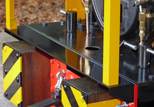
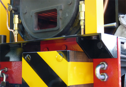
as ending up with sore hands from using files for almost 7 hours).As previously mentioned the four mounting holes had to match the existing buffer beam mounting bolt positions, so various paper templates were cut and fitted to the buffer beam until they correctly fitted around the existing bolts. The paper template was then used to mark out the footplate extension for drilling. Several months passed between making the footplate extension and finally fitting to the loco after all the cab parts had been painted, so I was quite relieved when it fitted correctly into place. The photos below show views of the completed footplate extension from above and below. They show how closely the extension fitted to the "bent" buffer beam and how it fits around the dumb buffers. You can also see that the top of the existing buffer beam has been painted black (it was red) so that the completed footplate does not have a red line across it. |
  |