 During
the first 2 1/2 years that I owned my Stafford I constantly had
problems with clack valves that would not reseat correctly and promptly
started emptying the boiler. This problem was not quite
unique to
my Stafford as I did witness it happen on another couple of Stafford's
on visiting engine days, but my Stafford seemed particularly prone to
clack failure. As a result I designed and built my own O Ring
clack valves, and from that day on I never had any further problems.
So as I was already modifying the injector system (see other
pages of this website) I decided to make a new pair of O Ring clacks
and fit them to the Feldbahn while the injector pipework was being
rebuilt. During
the first 2 1/2 years that I owned my Stafford I constantly had
problems with clack valves that would not reseat correctly and promptly
started emptying the boiler. This problem was not quite
unique to
my Stafford as I did witness it happen on another couple of Stafford's
on visiting engine days, but my Stafford seemed particularly prone to
clack failure. As a result I designed and built my own O Ring
clack valves, and from that day on I never had any further problems.
So as I was already modifying the injector system (see other
pages of this website) I decided to make a new pair of O Ring clacks
and fit them to the Feldbahn while the injector pipework was being
rebuilt.
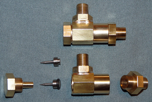
The photo on the left shows the parts of the O Ring
clack valve and shows the shuttle "as machined" and when fitted with
its O Ring. All the parts other than the shuttle, which is
Stainless Steel, are made from Phosphor Bronze and the O Ring is VITON
to withstand the temperature of the boiling water (172 degrees
Centigrade at 120 psi). Both the top
and bottom caps of the valve can easily be removed for cleaning, and as
the O Ring seat is on the face of the bottom cap there is no difficult
machining of blind holes / valve seats to do. It takes me
about 1
1/2 days in the workshop to make a pair of valves but their performance
is superb and having used them for 18 months on my Stafford I am
convinced of their superiority over normal ball valve clacks.
The
only downside is that the O Rings need to be replaced after about 50
hours use as they tend to flatten and leak when there is no
boiler pressure (e.g.
before steam is raised).
O
Ring clack valves require the shuttle that carries the O Ring to be
guided as it moves
up and down (open / closed) so that the O Ring will seat around the
hole in the inlet, unlike a ball bearing valve where the loose ball
simply
drops into the hole. This can be accomplished by having a
fluted
stem on the shuttle which slides up and down in the inlet port bore but
that requires the inlet bore to be increased beyond the feed pipe bore
so that the area available for the water to flow is maintained.
This will obviously increase the dimensions of the clack
valve.
To overcome this size increase I decided to put the shuttle
stem
on the top of the shuttle and guide it by using a tubular extension of
the valves top cap. The length and tapered end of the shuttle
stem were made so that the stem could be engaged in the caps guide hole
before the cap is screwed down to ease maintenance of the valve, and
obviously the guide hole in the cap has an opening into the valve
chamber at its upper end to avoid any possibility of the shuttle stem
becoming hydraulically locked as it moves up into the guide hole.
Full details of the O Ring
clack valve can be obtained by
downloading a JPEG copy of the CAD drawings from the Stafford section
of this website by clicking
here
(use a
"right click" and "save as" to download the image to your computer). |