 |
 |
Current Model Engineering
Projects
 The
Winson's Steam Lorry The
Winson's Steam LorryThis was the model that got me back into model engineering after a decade of building full size 4x4s, and according to the advertisements it would "only require simple hand tools to complete this superb kit". "Designed on CAD and manufactured using CAM" said the adverts, so according to my engineering background that should have ensured that all the parts would fit together and that the quality of the machining should have been very good. At that time my only machine tool was an ancient Unimat SL lathe (only suitable for miniature model work) that I had owned for over 30 years, so building a kit was about the only way that I could ever hope to make a live steam model. So I paid the substantial deposit and awaited the first of the twelve monthly kits (paid for by further instalments). I knew that I was in for trouble as soon as the first kit arrived when I inspected the contents. One of the first parts I unwrapped was a differential shaft that had a turned section on which gears should have rotated. As this had a rougher surface finish than my small hand file it obviously wasn't going to work. The more bits I examined the more problems I found. Thinking back 30 years to when I was in the AEC Trucks training workshops I remembered seeing the instructors beating apprentices work to scrap with a large hammer and then telling them to fix the part again (not make another one, FIX IT), and all because the work was not perfect. What those instructors would have thought of the standard of Winson's work is probably best left unsaid. |
||
 As
the months went by I accumulated an ever bigger pile of "scrap", and it
was impossible to keep up with the supposed "one kit a month" assembly
rate as so many parts had to be returned to Winson's for replacement.
Unfortunately for me and many others, but not for any
potential
future customers, Winson's went bust long before my steam lorry was
complete. This created a big problem as none of the builders
could now get the parts they needed to complete their models. As
the months went by I accumulated an ever bigger pile of "scrap", and it
was impossible to keep up with the supposed "one kit a month" assembly
rate as so many parts had to be returned to Winson's for replacement.
Unfortunately for me and many others, but not for any
potential
future customers, Winson's went bust long before my steam lorry was
complete. This created a big problem as none of the builders
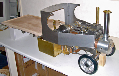
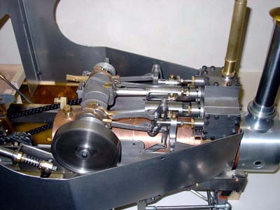
could now get the parts they needed to complete their models.I soldiered on for a couple of years, remaking almost every part of the kit using my tiny lathe and hand tools. When the parts were too big for my Unimat, or required milling, I was fortunate to have found a local "one man" engineering company who was happy to sort out the parts for me really cheaply when he had spare time between paying jobs. The photo on the right shows how far we managed to progress, but eventually the engineers company closed and I was stuck with an incomplete kit. To give you an idea of the scale of Winson's problems, the crankshaft big end bearing surfaces weren't even circular in section and had tapers across their width. All I could do was file them with needle files and use Engineers Blue in the big end bearings to show me where to file next until they ran true. Another big problem was the trunk guide for one cylinder where, using the trunk guide bore as a reference, the piston rod hole turned out to be on a different centre line with the cylinder locating boss on yet another. The end result was a piston that didn't sit in the centre of the cylinder and that moved in an arc instead of a straight line. Eventually I decided that even if I did spend a few more years trying to complete the thing it probably wouldn't work too well anyway as a result of all the poor parts that it was built from. So when I saw a working traction engine for sale at the Guildford Model Engineering Society annual exhibition I decided to purchase it and get rid of the steam lorry. |
||
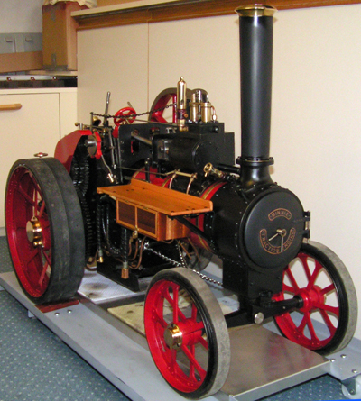 'Dot' a 2" scale Minnie Traction
Engine 'Dot' a 2" scale Minnie Traction
EngineThis little traction engine is the double size version of the Minnie traction engine, an easy to build nominally 1/12th of full size model. Scaling it up to twice the designed size results in an engine about 1 metre long with sufficient power to pull its driver on a trailer across the rough grass of a rally field. As mentioned above I first saw this engine for sale at the Guildford Model Engineering Society annual exhibition where I had a long talk with its owner. I was even offered a drive, but declined as I wasn't dressed for getting dirty, although I never made an enquiry about buying it. After a week of thinking about the engine I eventually decided that maybe it was what I wanted, so I then had to find out who the seller was. Thankfully the Guildford MES could put me in touch with the seller (who turned out to be R Chambers, a well known model boiler maker) and two weeks later the engine and its driving / passenger trolley arrived home in the back of my car. At the time I wasn't an active member of any model engineering society, so I had to set about learning how to operate it the hard way. And hard it was, because as I later found out small engines are harder to drive than larger ones. However in the end with the guidance of another model traction engine owner I did succeed, and for several years I had a lot of fun with 'Dot' as the engine was named by its builder. I even managed to use the engine to give children rides on its trailer at the village fete although it really struggled to pull a load consisting of me plus two or three kids. It's most memorable occasion at the village fete was when a spark from the funnel set a straw bale marking the centre show ring alight, which the exhibiting firemen and their engine then proceeded to use as a fire fighting demonstration. Over the years I added a few parts to the engine, the wooden "shelf" and / storage box and the water pick up hose being some of them, and I also had to frequently glue the rubber tyre back on to the rear wheels. Other than that the engine ran well until I eventually traded it in to buy a larger version that would be more comfortable to drive and have more pulling power. |
||
 Battery
electric 5" gauge Class
90 'Mission Impossible' Battery
electric 5" gauge Class
90 'Mission Impossible'The next project came about because I had joined a model engineering society in order to get the traction engines annual boiler test done. The society had more members building and running railway locos than traction engines, so to be able to join in I decided to build a 5" gauge battery electric loco. This was supposed to be a "quick build" project, and in fact the chassis was taken for a test run on the Basingstoke & District Model Engineering Society track about four months into the build, as shown in the photo on the right. Because the loco was to be electrically powered I thought that it should be a model of an electric loco, so I chose a Class 90. Research on the Internet provided plenty of photos from which I was able to draw up the parts to detail the model, and also provided the choice of name "Mission Impossible". The real loco was the first loco of Richard Branson's attempt to run a railway, and presumably in view of the difficulties he saw in the venture (and the film of the name) he called it Mission Impossible. Unfortunately for me the name seems all to true as the loco still isn't finished after seven years. The amount of detail required is huge, and the steam engines have always taken up too much time to have any left over to work on this model. |
||
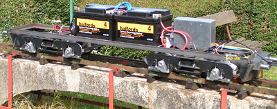
Electric loco driving trolley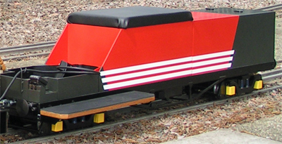 In order to run the Class 90
electric loco I required a driving trolley, and initially I built a
simple four wheeled "skate" to ride on. Unfortunately this
only lasted for a few miles before a wheel bearing support broke, and
the resulting accident as the truck derailed destroyed so much (and a
redesign to use different bearings would have been quite difficult)
that I decided to scrap the thing. The result was that I
bought a 4 foot bogie chassis from Polly Model Engineering (see the
Links page for details) and fitted it with my own top. It was
painted in the Virgin Rail colour scheme ready for the Class 90, and
had a large water tank in the rear and space for coal at the front so
that it could be used with the Polly I steam loco in the next section. In order to run the Class 90
electric loco I required a driving trolley, and initially I built a
simple four wheeled "skate" to ride on. Unfortunately this
only lasted for a few miles before a wheel bearing support broke, and
the resulting accident as the truck derailed destroyed so much (and a
redesign to use different bearings would have been quite difficult)
that I decided to scrap the thing. The result was that I
bought a 4 foot bogie chassis from Polly Model Engineering (see the
Links page for details) and fitted it with my own top. It was
painted in the Virgin Rail colour scheme ready for the Class 90, and
had a large water tank in the rear and space for coal at the front so
that it could be used with the Polly I steam loco in the next section.Alterations to the trolley were the sub frame bars which are just visible in the photo, interchangeable foot rests (for ground level or raised tracks), and a compensated brake linkage to ensure that both bogies brakes received an equal share of the braking effort. |
||
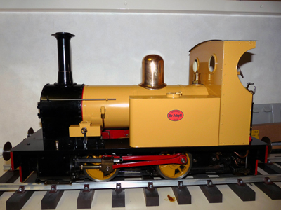 5" gauge Polly I steam locomotive 5" gauge Polly I steam locomotiveA couple of years into the build of the Class 90, and while still owning 'Dot' the traction engine I purchased this used Polly I steam loco so that I would have something to run with my fellow club members. The Polly series of steam engines are available as kits from Polly Model Engineering (see the Links page for more details), and unlike the Winson's offerings they are proven designs of very high quality that actually work. For a variety of reasons I rarely found time to run the engine, and eventually it was sold when I purchased my 7 1/4" gauge Stafford steam locomotive. |
||
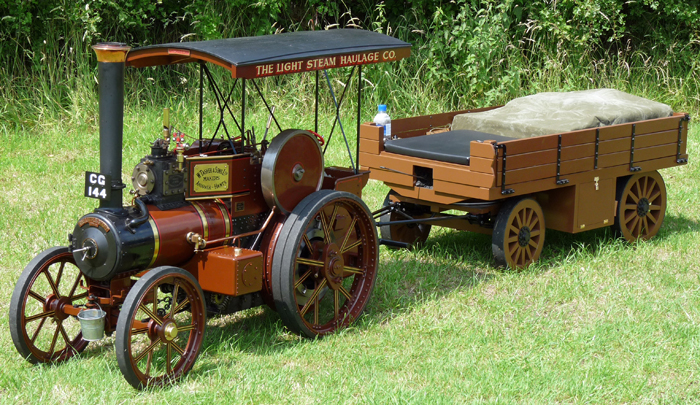 4" scale (1/3rd full size) Tasker A2 traction engine 'Perseverance' This is where things started to get somewhat bigger, with the sale of 'Dot' (the 2" scale Minnie traction engine) and the purchase of this 4" scale Tasker A2 traction engine. It had been built by a very good model engineer named Roy Masters who only sold it when he finished building another Tasker almost twice the size of this one. It was about 5 feet long (1.5 metres) and weighed over 1/4 of a Ton, so it needed a van to transport it together with its trailers. This model was an absolute delight to drive, being very easy to fire and having plenty of power to pull the heaviest loads. It's shown in the photo with the traction wagon I built for it, and I always thought that it showed the model to its best advantage. Most model traction engines run with pretty hideous contraptions behind them to carry their driver and or passengers, but this wagon looks far more like the wagons pulled by the real working traction engines. The wagon had enough coal under the front seat for a day's running, space in the middle for a picnic cool box and tools, and a 45 litre water tank in the back (with an electric pump to move the water to the engines tender). I also had a much larger trailer for use at the village fete that could carry me plus about 6 kids (or 2 adults and 4 small kids) which came in useful on the rare occasion that I attended a rally with a friend. I ran this engine for three years, and it never gave me any problems other than when it shed its rear tyres. As with the Minnie traction engine gluing them back on was a filthy job, with the added problem that this engine needed a jack to be used before you could get the wheel off ! Named 'Perseverance' by its builder the engine proved to be very popular at rallies, and I found myself with more invites to events than I could manage to attend. But it was at these events that I began to notice a problem; the events were all rather lonely when compared to the time I spent at the Pinewood Miniature Railway track. Once the traction engine was fired up I normally ended up pottering around a rally field all day and occasionally chatting to other modellers or visitors, but as I never had a caravan to stay for the weekend I always seemed to be an outsider at the traction engine rallies. At the railway I was one of the group, and acted as a guard on their trains. It was also obvious that the constant return to the stations made for a more social day out. I also realised that I enjoyed the Tasker most when actually working it to give rides, something that happens all the time on a railway but rarely with traction engines. It's the challenge of having to keep the engine running at its best to provide the public service that gives me far more pleasure than just pottering about. So after three years this absolutely superb traction engine was sold and replaced by the Stafford saddle tank locomotive that enabled me to become an owner driver at the Pinewood track public running days. The Tasker is by far and away the most beautiful piece of model engineering that I have ever had the pleasure to own, but the Stafford steam locomotive that replaced it is giving me a lot more fun. You can see a short video of the Tasker running at the annual Exbury Gardens "Steam in the Gardens" rally by clicking on the box below. |
||
|
|
||
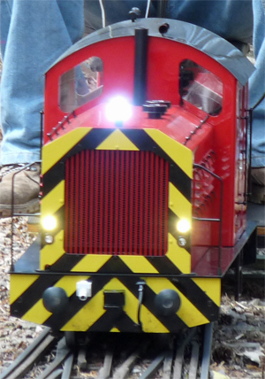
5" gauge Ride on Railways
'Hercules'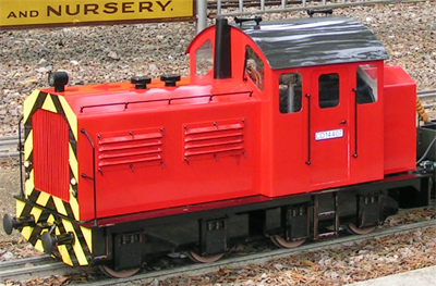 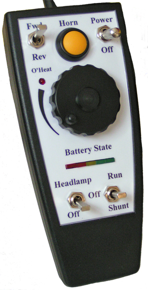 This
loco was built in just 10 weeks during the winter after purchasing the
Tasker A2 traction engine so that I would have something to run when at
the Pinewood society member's days. It is supplied as a kit
by
Ride on Railways (see the Links page for details) and was the 35th
example they had built, although at the time of writing this they have
sold over 100. This
loco was built in just 10 weeks during the winter after purchasing the
Tasker A2 traction engine so that I would have something to run when at
the Pinewood society member's days. It is supplied as a kit
by
Ride on Railways (see the Links page for details) and was the 35th
example they had built, although at the time of writing this they have
sold over 100.The kit was a delight to assemble as every part was well made and finished so well that no smoothing or other trimming was required. As usual I chose to have all the major parts grit blasted before painting, but that was all the kit required to achieve the finish shown in the photos. To "customise" the loco I added the engine louvres, hand rails, lights, bonnet and buffer fittings, and a new design of radiator grille. The loco also features a diesel engine sound effect unit which includes the engine start noises. You can see and hear this in the very short video by clicking on the image below. A large array of LED lighting was also installed so that the running lights could be switched for shunting or track running and the headlight could be used when in tunnels (or driving at night). All of these lights automatically swap ends if the loco is run the opposite way round to that shown in the photo. To control all of this a special hand controller had to be built to opearte the 4QD controller (see the Links page for details) supplied with the kit, and this is shown to the right. Power is supplied by two "over size" (according to Ride on railways suggestions) 12 Volt batteries to four electric motors giving almost one horsepower. As a result the loco weighs more than most other Hercules which gives it a little more traction, and it is quite happy when given the chance to pull two loaded passenger coaches. Its top speed is also quite close to 11 mph, which is more than enough to scare most drivers. I have been running the Hercules for four years now with only one problem when some driving wheels came loose on their axles. My solution to this problem is available to read by clicking here, and I would recommend anyone building a kit to incorporate the idea during the initial build rather than having to do it later when something has gone wrong. |
||
|
||
7 1/4" gauge driving trolley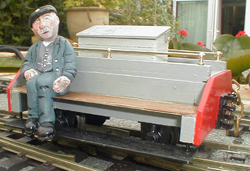 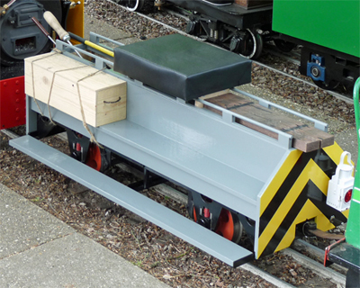 This
odd little photo (left)
that I found on the Internet became the inspiration for the driving
truck (right) that I built to go with my 7 1/4" gauge Stafford steam
locomotive. The thought of quarry workers riding on the wagon
behind a steam loco looking rather like a Stafford was rather
appealing, and the wagon had the added benefit that the passengers
footboards would also fit my feet. So a design was worked up
on my CAD package to use PNP Railways (see the Links page for details)
narrow gauge wheels and axles with the rest of the wagon being made by
me. The frames and spacers were laser cut by The Model
Engineers Laser (see the Links page for details), and once these were
welded up most of the rest of the work was in wood. The old
crate on the front left opens internally into the coal space at the
front of the wagon to increase the coal capacity, which is normally
sufficient for about 3 hours running. The seat is removable,
just in case I ever fit a scale passenger to take some photos, and the
two old sleepers loaded on the back cover up a storage space for the
oil can etc. Another puzzle to most people is why it has a
model sledge hammer onboard. The answer being, it operates
the handbrake working on all four wagon wheels via a compensating
linkage. It is coupled to the Stafford locomotive's solid
steel
drawbar using an 8mm diameter pin with 'R' clip to stop the pin from
falling out, and a safety chain connects the loco and wagon using a
separately mounted 'U' bolt on the wagon. This
odd little photo (left)
that I found on the Internet became the inspiration for the driving
truck (right) that I built to go with my 7 1/4" gauge Stafford steam
locomotive. The thought of quarry workers riding on the wagon
behind a steam loco looking rather like a Stafford was rather
appealing, and the wagon had the added benefit that the passengers
footboards would also fit my feet. So a design was worked up
on my CAD package to use PNP Railways (see the Links page for details)
narrow gauge wheels and axles with the rest of the wagon being made by
me. The frames and spacers were laser cut by The Model
Engineers Laser (see the Links page for details), and once these were
welded up most of the rest of the work was in wood. The old
crate on the front left opens internally into the coal space at the
front of the wagon to increase the coal capacity, which is normally
sufficient for about 3 hours running. The seat is removable,
just in case I ever fit a scale passenger to take some photos, and the
two old sleepers loaded on the back cover up a storage space for the
oil can etc. Another puzzle to most people is why it has a
model sledge hammer onboard. The answer being, it operates
the handbrake working on all four wagon wheels via a compensating
linkage. It is coupled to the Stafford locomotive's solid
steel
drawbar using an 8mm diameter pin with 'R' clip to stop the pin from
falling out, and a safety chain connects the loco and wagon using a
separately mounted 'U' bolt on the wagon. |
||
 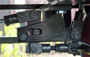 The
photo on the right shows
the brake compensating linkage, with the operating handle (sledge
hammer) pulling the almost vertical link at the right of the image.
The two brake push rods are connected to the top and bottom
of the crank, which can slide in the slotted pivots to balance the
brake loads. The
photo on the right shows
the brake compensating linkage, with the operating handle (sledge
hammer) pulling the almost vertical link at the right of the image.
The two brake push rods are connected to the top and bottom
of the crank, which can slide in the slotted pivots to balance the
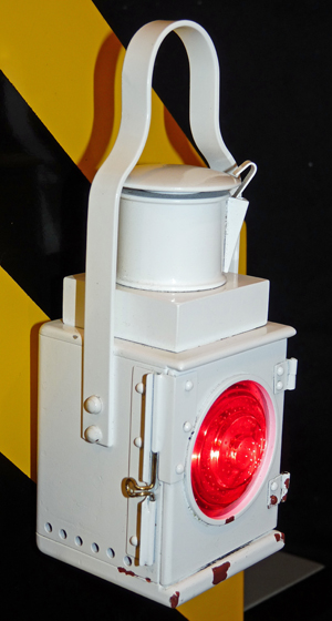
brake loads.The photo on the left shows the detail of the wagons tail lamp, which was built in about a day mainly from scrap. The lens was originally a Land Rover tail lamp, which being plastic is easily turned to reduce the diameter to fit the lamp, and three red LEDs provide the illumination. The main body was turned from a short length of 50mm square aluminium box section, and all the other parts fit together rather like one of those wooden block puzzles so that only a single screw in the bottom holds the whole thing together. It's mounting to the wagon is its strongest part using an M6 bolt to stop the young passengers on the adjacent passenger coach from removing it. |
||
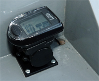 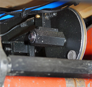 The
most frequently asked
question about my driving trolleys is "how do you make the speedo read
properly", and this photo shows how I do it. The
most frequently asked
question about my driving trolleys is "how do you make the speedo read
properly", and this photo shows how I do it.In my experience every cycle computer is supplied with two calibration charts, one showing the calibration against wheel diameter and the other against wheel circumference which is the one we need to use. The problem we need to solve is that the wheels of our wagons etc, are far too small for the cycle wheels that the computers are designed for with the result that the speed shown is far too high. So all you need to do is "gear" the drive down to correct the problem, and that can be done quite simply by driving a "wheel" from your wagon axle. The right hand photo shows the wagon axle painted red at the bottom with an unpainted section on which the "wheel" runs. The "wheel" is supported on a pivoted arm from the chassis with a light spring to keep it pressing down on the axle, and a large 'O' ring acts as a tyre to give the "wheel" grip on the axle. On my version here the "wheel" shaft runs in two small sealed ball bearings. The important thing to remember is that the cycle speedometers use magnetic pickups, so the wheel and the mounts for the probe (the cylindrical thing with a wire coming out of its left hand end) must be made of non ferrous materials. I used aluminium for the "wheel" and brass for everything else. The difficut bit is to get the diameters of the "wheel" and axle correct to make the cycle computer believe it is sensing the rotation of a normal wheel. So if you remember your old school maths you can calculate the circumference of your wagons wheel at its rolling diameter (don't forget that railway wheels are "coned"). Now pick a wheel circumference close to the shortest from the computers calibration chart, and divide this number by the circumference of you wagons wheel. If you multiply the axle diameter by this number you will have found the diameter required for your "wheel". Obviously you need to allow for how you fit the "tyre" onto your wheel, but the solution to speedo calibration is very easy. |
||
The Hymek Project 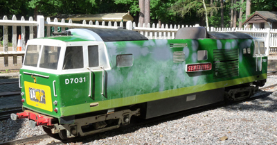 In
the middle of 2013 there seemed to be a shortage of engines for pulling
the passenger trains at Pinewood Miniature Railway where I was
operating my Stafford 'Gentoo', and this coincided with the chance to
purchase a Mardyke Hymek petrol hydraulic locomotive. A test
drive gave the impression that the loco ran very well, and although it
obviously needed a repaint and new wheel sets the loco very quickly
moved to it's new home at Pinewood. A week later both bogies
had
been removed and the body fully stripped out ready for the renovation
to start. If only that rate of progress could have been
maintained ! The amount of work needed escalated with every
part
examined, and the project quickly reached the stage where it became
worthy of its own webpage. If
you are interested you can read
all
about it by clicking here. In
the middle of 2013 there seemed to be a shortage of engines for pulling
the passenger trains at Pinewood Miniature Railway where I was
operating my Stafford 'Gentoo', and this coincided with the chance to
purchase a Mardyke Hymek petrol hydraulic locomotive. A test
drive gave the impression that the loco ran very well, and although it
obviously needed a repaint and new wheel sets the loco very quickly
moved to it's new home at Pinewood. A week later both bogies
had
been removed and the body fully stripped out ready for the renovation
to start. If only that rate of progress could have been
maintained ! The amount of work needed escalated with every
part
examined, and the project quickly reached the stage where it became
worthy of its own webpage. If
you are interested you can read
all
about it by clicking here. |
||
My Workshop 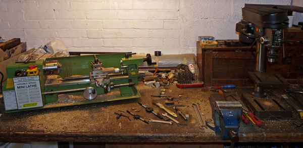 This final photo shows my small Warco lathe and pillar drill, on which all the parts of these projects have been made. Together with my MIG welder and a large propane torch they are adequate for nearly everything I need to do, and on those odd occasions when better facilities are needed I can normally find a local engineering company to help out. |