 |
 |
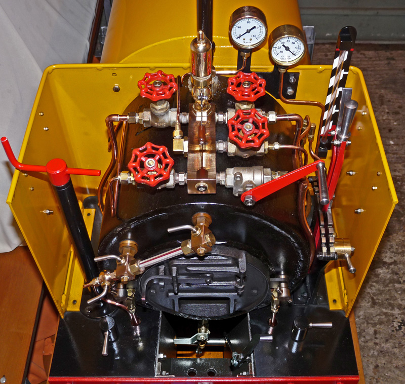
The Controls
| The
Stafford class saddle tank has been designed to be easy to operate but
still has a lot of controls that you will need to understand if you are
to operate the locomotive safely and efficiently. This page
shows
where the controls described on other pages throughout this website are
located on the loco, and gives an introduction to their use. Point at a
control to see its name, or "click" on a control to read about
it.
Alternatively
the controls are listed further down this page in alphabetical order
together with information about their function and use.
|
|
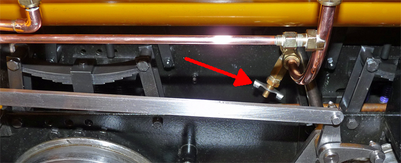 The saddle tank drain cock is shown by the arrow in the photo above. Take care when
operating the saddle tank drain cock. To avoid touching the
main
steam pipe (which can be very hot) it is best to always approach the
drain cock from the left-hand side of the loco. Also, the
drain
cock seems to operate back to front when compared to a "normal"
household tap. The problem arises when you attempt to close
the
drain cock by rotating it the wrong way, because as you continue to
turn it you will force the operating arm off its shaft without even
noticing. Once off it is almost impossible to fix the arm
back
into place and you will probably have to fit a new drain cock.
The simple check is to watch the silver coloured lever as you rotate it. The lever should get further away from the body of the drain cock as you close the cock, NEVER turn the cock so far that the lever touches the body. |
| Blowdown
Valve. Purpose. The purpose of a boiler blowdown is to control the solids in the boiler water (such as the calcium that forms limescale in the boiler). Correct use of a blowdown helps to protect the boiler surfaces from severe scaling or corrosion problems that may occur if the boiler is simply left full of water. Use. The blowdown valve is used to drain the water from the boiler, but also serves as a useful point to connect a hose when filling the boiler with water at the start of a day. CAUTION. NEVER TRY TO FILL THE BOILER USING THE BLOWDOWN VALVE IF THE BOILER IS EVEN SLIGHTLY HOT. During normal operation of the Stafford this valve will always be kept closed (the lever is in the horizontal position as shown in the photo), but when you have finished using the loco it may be used to drain the water from the boiler. ALWAYS make sure that the fire is out (I prefer to shovel all the burning coal out via the firebox door) before you drain the boiler. Then use the residual steam in the boiler to operate an injector to raise the water level to the top of the sight glass so that as much of the internal surface of the boiler as possible will benefit from the blowdown. WAIT until the boiler pressure has dropped to about 45 psi and then carefully open the blowdown valve. Scalding steam and water will be blasted downwards from the valve, so if possible have the loco over an inspection pit (or on a raised track). When the flow of steam and water has stopped the other steam control valves on the boiler should also be opened, and all the valves will normally be left open when the loco is being stored. The residual heat of the boiler will thoroughly dry the insides of the boiler to help prevent rusting during storage. |
| Boiler Pressure Gauge. Purpose. To display the steam pressure in the boiler in Pounds per Square Inch (psi). Use. The Stafford locomotive has a steel boiler rated for use at a maximum pressure of 120 psi. It is essential that this boiler pressure is never exceeded so a red mark is painted onto the pressure gauge dial to clearly show the maximum safe pressure and the safety valve is also calibrated to open and release excess steam when 120 psi is reached. Both the red mark and the operation of the safety valve will be checked every year by your official boiler inspector. In practice you can easily pull most sensible passenger trains with anything over 80 psi, although the higher the running pressure in the boiler the more power you will have available and the more efficiently the loco will operate. |
| Cylinder
Drain Cock Lever. Purpose. The cylinder drain cock lever operates all four cylinder drain cocks (two underneath each cylinder) to allow condensed steam that will occur when the cylinders are cold to escape from the cylinders (and to prevent hydraulic locks which could damage the cylinders). Use. Whenever the cylinders of the loco may be below normal running temperature (e.g. at the start of any days running or if the loco has been stopped in the station for several minutes) the drain cock operating lever should be pushed as far as it will go towards the boiler before the regulator is opened to start the loco moving. NOTE: On later versions of the Stafford (those with a slide rather than the rotating lever) the action has been reversed and the lever is pulled all the way back to open the drain cocks. After a while, which will vary depending upon the temperature of the cylinders, the operating lever should be pulled fully back to close the drain cocks. As a general guide, if any water is being blown out of the drain cocks they should be left open, but when only steam is coming out they may be closed. If you close them too soon you will be able to hear a harsh "thump" with every piston stroke as the piston hits water in the cylinder. This noise will also occur if you have over filled the boiler with water when the steam flow to the cylinders "pulls" boiler water with it. This condition is called PRIMING, and if it occurs you should immediately open the drain cocks until the boiler water level has reduced to a normal level (below 3/4 sight glass). |
| Firebox Air Inlet. Purpose. This inlet simply allows air to flow into the firebox underneath the grate to allow the fire to burn. Use. Unlike many steam engines the Stafford class locomotive does not have an adjustable damper fitted to the firebox air inlet to control the amount of air reaching the fire (and thus how well the fire burns) as during the locos development Station Road Steam found that a damper was unnecessary. As a result the driver of a Stafford will only be using this opening to shovel ash out of the bottom of the firebox. The Stafford driver should regularly check the level of the ash accumulating in the bottom of the firebox, and if it starts to build up the excess ash should be shovelled out to ensure free flow of air to the fire. Excess ash is likely to occur whenever the fire is raked. |
| Fire Door. Purpose. The fire door is used to add coal (or other combustibles) to the fire and to permit the driver to rake the fire in order to break up any clinker that may be forming on the grate. During normal operation the fire door will be firmly shut. Use. When adding coal to the fire the driver needs to try to spread an even layer over the entire area of the grate. The aim is to have a brightly burning fire over the entire area of the grate, and to add new coal in a "little and often" fashion evenly over the fire, to keep the level of the top of the fire just above the bottom of the firebox doorsill. As soon as the coal has been added the firebox door should be shut to ensure that cold air is not pulled in through the open door which would reduce the amount of steam the boiler creates. The exception to keeping the door closed is if the loco is working very hard up an extremely long hill, or after working hard pulling a loaded train has to wait at a signal or in a station. Under these conditions the very hot fire may produce so much steam that the boiler pressure may get close to the 120 psi at which the safety valve will open. Before this occurs the driver should, if the water level permits, add more water to the boiler using the injectors to "cool things down a bit" but in some circumstances it may be helpful to leave the firebox door slightly open to admit some cool air. NOTE: Later versions of the Stafford have a second latch position for the firebox door to help you with this. The use of the injectors is best because you will use the excess heat to rapidly warm up the cold water you added to the boiler, but a slightly open firebox door will also give you some additional control over the amount of steam the boiler is generating. Fire Door Latch. Purpose Simply to keep the firebox door closed. Use. When the Stafford is operating this latch will get extremely; hot so always use a suitable glove, piece of rag, or the coal shovel to lift the latch and to open the firebox door. |
| Firebox Cover Thumbscrew. Purpose. On the Stafford class locomotives the entire fire grate and firebox cover plate (with the firebox door and air inlet in it) can be removed for cleaning out the firebox as a single unit. This assembly is held in place by two thumbscrews, one on either side, which screw onto studs protruding from the boiler. Use. When the thumbscrews are cool enough to touch, simply unscrew and remove them. The firebox cover plate with the grate attached can then be pulled out of the firebox to give very easy access to the fire tubes for cleaning. |
| Handbrake. Purpose. The handbrake is the only means of braking that operates on the Stafford locomotive, as even if you have the vacuum brake option fitted this does not operate the locomotive brakes. Use. The handbrake is applied by rotating the handle clockwise and released by turning it anticlockwise until you feel it stop turning. The more you wind the handle clockwise the harder the brakes will be applied, but if you are pulling a heavily loaded train you may find that the Stafford's wheels just stop rotating and the wheels slide along the track. This is why the vacuum brakes are available as an option so that you (as driver of the train) can apply braking to actual train behind your locomotive. The handbrake has brake shoes operating on the two rear wheels of the locomotive, and the brake force is thus also applied to the front wheels via the connecting rods. You must however remember that the Stafford by itself weighs almost a 1/4 of a Ton, and with a loaded train behind it the weight could easily be a Ton or more, and all this weight has to be stopped by the grip of steel wheels on the track. It is essential that you plan ahead and start slowing down in plenty of time to reach a safe speed for corners or when trying to stop in a station. |
| Injector Clack Valve. Purpose. Clack valves are a very simple automatic valve that is used to stop water escaping from the boiler but still allow you to pump more water in. If you look inside the valve (NEVER remove the cover if the boiler has pressure in it) you will see a small stainless steel ball that rests over a hole. The boiler pressure pushes the ball onto the edges of the hole which stops the water going past, but if water at higher pressure is fed through the pipe underneath the ball the ball will lift up to let the water into the boiler. When the water feed is stopped the ball drops back and seals the hole up again. Use. The clack valve is automatic so the driver has nothing to do, other than clean the valve during routine maintenance when the loco is not "in steam". The Stafford locomotive has two injector clack valves fitted on the boiler, one to either side of the firebox cover plate. Injector Steam Valve. Purpose. To control the flow of steam to either of the two injectors fitted to the locomotive which are used to "pump" water into the boiler. Two steam valves are fitted to the Stafford locomotive (one on either side of the top of the boiler) to supply steam to the two injectors (one on either side of the chassis underneath the cab). Use. The steam valve is always turned on after the relevant injector water valve, and off after the water valve. When the valve is open, steam will flow to the relevant injector and water should be "pumped" from the saddle tank into the boiler. See the next paragraphs for more information about Injectors. When closing the valve never over tighten it as doing so may damage the valve seat and cause the valve to leak. All the steam control valves on the Stafford only need to be turned gently to close them. Injector. Purpose. To move water from the saddle tank into the boiler of the Stafford locomotive. You don't actually need to know how an injector works (but if you are interested "Google" boiler injector and read about it on Wikipedia or in countless other articles), but it's an almost magic device. Boiler steam goes in one hole, water from the saddle tank into another; a third is a water overflow, and the fourth hole goes to the boiler. When the water and steam are turned on, by magic (actually the laws of physics and the use of some very clever and accurately made miniature cones) the steam from the boiler will actually "pump" water into the boiler against the same pressure of the steam that is making the injector work. Use. The Stafford's are fitted with two injectors (one on either side of the chassis underneath the cab), and these are the only way of getting water into the boiler when operating the loco. To comply with the insurance requirements of any club or society it is mandatory that at all times you have two working methods of getting water into the boiler of a working model steam locomotive, and for your own (and others) safety you should comply with this requirement even if you are running the loco on your own private premises. So it is important to maintain the two injector systems in working order and to understand how to operate them. Injector System Operation. To operate either injector you need to have water in the saddle tank and a boiler pressure of more than about 40 psi. First turn on the relevant (left or right) injector water supply using the valve on the footplate (see paragraphs below) and look to see that the water is flowing out of the injector overflow pipe. If you haven't got a steady flow of water running onto the track it may be because the saddle tank is nearly empty, or you may have a blockage in a pipe or the injector (which can only really be cleared when the loco is not "in steam"). If the water is running nicely, slowly open the relevant (left or right) injector steam valve and as soon as the water overflow seems to cease quickly open the steam valve a few turns. When everything goes right you will see that almost no water (or steam) flows out of the overflow pipe and you will be able to hear the injector "sing" (a sort of whistling gurgle) as it forces water into the boiler. If this doesn't happen you will almost certainly have clouds of steam and hot water billowing out of the injector overflow. Just turn off the relevant injector steam valve, wait a few seconds for the overflow water to settle down again, and then try opening the steam valve again. It takes practice to get it right first time, and even then occasionally you may need more than one attempt to start an injector. Once the injector is working just leave it running until the water level is up to your desired level on the sight glass (see the information about the sight glass in later paragraphs), then turn off the steam followed by turning off the water. UPDATE. At some point Station Road Steam started fitting injectors of a different type to those on my Stafford 'Gentoo', and as I found out when I purchased my Feldbahn (four years after originally writing this page) they seem to need to be operated in a different way to that described above. When I first fired up my Feldbahn I could not get either injector to work using the method described above which had been so successful with 'Gentoo'. The method shown to me that works well on the Feldbahn is to fully open the injector water valve and then open the injector steam valve (a turn or two). The injector will probably not have started at this point, so slowly close the injector water valve until the injector starts (all the overflow from the injector suddenly ceases) at which point the water valve may be gently opened up again. Quite why this operating method is required is unknown to me; but it certainly works for me and another Feldbahn owner who had no luck with his injectors until I emailed this technique to him. The worst case scenario with injectors is when one fails to start and, even after you have closed the relevant injector steam valve, steam and water continue to blast out of the injector overflow pipe (and bubbling noises can be heard in the saddle tank). This indicates that the ball in injector clack valve has not seated properly, with the result that the boiler pressure is pushing the water out of the boiler past the stuck clack valve. If it happens, don't panic. Try going through the motions of restarting the injector, but most likely the situation will not change. Most importantly keep an eye on the boiler water level using the sight glass, but if the level gets close to the bottom then very quickly shovel out all of the fire from the firebox (remembering to "dump" the burning embers safely and where they won't start a fire). A boiler without water but with a good fire will very quickly be damaged. Some people try tapping the stuck injector clack valve with their shovel in the hope that the ball may drop back onto its seat. Try to start the other injector to help keep the boiler water level up, and if at all possible pour cold water over the injector from which the steam and water is rushing out to try to cool it. Injectors heated by steam rushing through them are much harder to get working than cold injectors. If you're lucky you may get the offending clack valve ball to reseat if you can get the relevant injector operating again, but from personal experience I would put that at about a 20% chance. Most often the only solution is to remove the fire, pack up and once home dismantle and clean the offending clack valve. If I ever find a better solution you will find that you will be able to "click here" to read about it. Injector Water Valve. Purpose. To control the flow of water to either of the two injectors fitted to the locomotive which are used to "pump" water into the boiler. Two water valves are fitted to the Stafford locomotive (one on either side of footplate behind the boiler) to supply water to the two injectors (one on either side of the chassis underneath the cab). Use. Both valves are "Off" when their levers are facing across the footplate (as is the right-hand one in the photo at the top of the page), and are turned "On" by turning the lever 90 degrees (as shown by the left-hand one in the photo at the top of this page). For more information about using these valves see the paragraphs above. |
| Regulator. Purpose. To control the speed of the locomotive. Use. The regulator is shut when moved fully to the right, and opened by rotating it anticlockwise to move the lever towards the left. The regulator should be moved slowly and smoothly (which is easy to do as it is a commercial ball valve), and if you hear the wheels of the locomotive start to spin when trying to pull a heavy train quickly close the regulator and gently open it again to a slightly lower setting. Driving "light engine" (no train of loaded coaches or wagons) is very easy due the smooth operation of the regulator valve, and I've never needed to fully open the regulator even when pulling heavy passenger trains. As for the Stafford's top speed; I wouldn't like to find out as 11.5 mph was quite scary enough for me. To slow the train down when running you will need to start closing, or even completely shutting, the regulator. However you must remember that a train is very heavy (a loaded passenger train could be up to a Ton) and that the brakes are not really very effective when compared to a car, so you need to think well ahead and start slowing up long before you reach a tight corner, point or station. |
| Reversing Lever. Purpose. To control the direction of the locomotive; and also to let the driver reduce the amount of steam used for every turn of the driving wheel to improve the efficiency of the loco, thus saving coal and water. Use. There is a small lever at the top of the reversing lever that has to be pulled before the reversing lever may be moved, and which will then "lock" the reversing lever into set positions. To start the Stafford going forwards, move the lever to the fully forward position before opening the regulator. To go backwards, simply move the reversing lever to the fully back position before opening the regulator. The centre position is the stop position, which should always be selected if the loco is to be stopped and left unattended. Once the loco is moving, say above 2 mph, you can move the lever towards the centre position by 2 notches which will stop the steam entering the cylinders well before the piston reaches the end of its stroke. The expansion of the steam in the cylinders will continue to drive the piston to the end, but the loco will be using much less steam (and hence coal and water). Don't forget that as you slow down you may need to move the reversing lever to the extreme position again in order to increase the locos power to be ready for speeding up again. Think of it as being like changing gear in a car; although it is working in a very different way to gears as you can see if you watch the linkages moving on either side of the loco when you move the reversing lever. The reversing lever has one more use, which can help you control the speed of a loaded (passenger) train on steep descents or when arriving in a station. Don't start putting it into reverse and spinning the wheels as you may have seen in the cinema because spinning wheels give you no control at all, and the whole train will just slide until it eventually stops. If you have already fully closed the regulator but the train is still starting to get faster on a descent (or not slowing fast enough as you enter a station) you can start moving the reversing lever towards the centre "stop" position and you will find that you will create some additional braking force. Be careful as if you over do it (or select reverse with the regulator not fully closed) you could make the wheels loose grip and start to slide or spin at which point you will no longer have control of the train. When pulling passenger trains without vacuum brakes I find this to be a useful technique, but it is no substitute for having vacuum train brakes which really improve everyone's safety. |
| Saddle Tank Water Level Gauge.
NOTE: This
is not a factory fit item, see the functional modifications section of
this
website. Purpose. To let the driver see how much water remains in the saddle tank without getting off the driving truck and opening the filler cap. Use. Just look at the indicated water level while the loco is on a level piece of track. |
| Saddle Tank Drain Cock.
See second photo at
the top of the page for position, operation, and "caution" notice.
NOTE:
Later versions of the Stafford do not have this drain cock
fitted. |
| Safety Valve. NOTE. The photo shows
the "exhaust pipe" of the safety valve which is actually a commercial
NABIC "pop valve" hidden behind the whistle in the photograph. Purpose. To limit the maximum pressure of the steam in the boiler to 120 psi by automatically opening to let steam escape if the pressure tries to rise any higher. Use. The safety valve is "factory set" and has no adjustments that the driver can use, other than a lever on top of the brass NABIC pop valve that may be operated (by lifting its outer end) to manually vent steam. |
| Boiler Water Level Sight Glass. Purpose. To show the level of the water inside the boiler. Note: This gauge will only indicate the correct water level when the loco is standing still on level track. You will need to take account of how much the water level changes up or down if the loco is on a hill. The level will also be somewhat erratic if you have just changed speed (or stopped) or when travelling over bumpy track because the water may be "sloshing around" inside the boiler. Use. The ideal boiler water level when the Stafford is standing still on level track is about 1/2 way up the sight glass. If the water is more than 3/4's full you have too much water in the boiler and may find that when you open the regulator to start moving the steam will drag boiler water with it into the cylinders, a condition called "priming" which in extreme cases could even lead to the pistons being unable to move as the cylinders fill with water. Opening the cylinder drain cocks will let the water escape, but the condition is best avoided by keeping better control of the water level in the boiler. Also as the boiler becomes more full with water there is less space to store steam, so even if you set off with the pressure gauge at 120 psi you may quickly find the boiler pressure falling as you use up all the stored steam in the boiler. Letting the water level get below 1/2 full is not really a problem until you get close to 1/4's full. Any less water and you are getting into the danger zone when the level may drop too low to cover the top of the firebox, and damage could be caused to the boiler. As mentioned earlier, when driving the loco the apparent water level will always be changing as the water sloshes around in the boiler, and if you are going uphill the sight glass will indicate more full than on level track. Likewise if you are going downhill the sight glass will indicate less water than when on level track. But at least railways don't slope as steeply as roads so it is not as difficult as keeping the correct water level in the boiler of a traction engine. |
| Sight Glass Drain Cock. Purpose. The sight glass drain cock is used to help you check the water level in the sight glass, or simply to help clean the inside of the sight glass if it looks a bit dirty while you are running. Use. This drain cock is shown in the closed position in the photo and is opened by rotating the silver coloured lever through 90 degrees (in either direction) from the position shown. If you open this drain cock when the boiler has pressure in it, the steam pressure will push all of the water out of the sight glass (taking any dirt with it). When the cock is closed again the water will quickly resume its correct level to show you how much water is in the boiler. Now if when you look at the sight glass you can't decide where the water level is you need to be able tell if it so high that it's above the top of the glass, or heaven forbid so low that it's out of sight at the bottom. The answer is to operate this drain cock and watch what happens to the water level as you open and then close it again. If the water level rushes down the glass tube and then up again you have simply overfilled the boiler, but if you don't see any water moving down and up in the glass tube then the water level is dangerously low and you need to use the injectors to get water in very quickly indeed. In fact if I ever reached this position I would immediately shovel all the fire out of the firebox as a safety precaution because a boiler with no water in it and a big fire under it will quickly be seriously damaged. |
| Sight
Glass Stop Cocks.
NOTE: These stop cocks must be open (in
the position shown in the photo) when the loco is being used. Purpose. To stop the contents of the boiler (water or steam) from getting into the sight glass if glass tube is broken. Use. Both the upper and lower stop cocks are shown in the photo in their open position, and must always be in this position to let water into the sight glass when the Stafford is to be used. The two cocks may be closed by rotating the silver coloured levers through 90 degrees (in either direction) from the position shown to stop the boiler water or steam from escaping if the sight glass is broken. Take great care if you ever have to use them in such a situation as the water will be at about 170 degrees Centigrade if the boiler pressure was 120 psi and you could easily scald yourself. Since these cocks are "safety critical" you should test that they can be rotated each time you start firing up your Stafford. |
| Steam Blower Valve. Purpose. To increase the draught through the funnel and thus draw more air through the fire to make it burn hotter. Use. Once you have lit the fire in the firebox the hot gasses produced by the burning coal will want to rise because they are lighter than cool air. To do so they will flow through the fire tubes in the boiler (heating the boiler water on their way) and then rise up through the funnel. As they do fresh air will be pulled in under the grate via the air inlet on the firebox cover plate, and the flow of air will enable the fire to burn. Then as the fire gets hotter, the gasses will also get hotter and want to rise faster and as a result they will heat the water quicker and also make the fire burn even hotter. But by themselves the hot gasses produced by the burning coal cannot create enough heat to raise as much steam as the loco needs. So to increase the flow of air through the fire the exhaust steam from the cylinders is directed up the funnel, and this blast of steam flowing up the funnel draws far more air through the fire to make it burn much hotter. Consequently the harder the loco is working the better the fire will burn and the more steam will be generated. This is great while the loco is moving and working, but when stopped (as at the station) it is necessary to keep sufficient air flowing to create the steam ready for when the loco next starts moving. To do this a small nozzle is pointed up the funnel beside the cylinder exhaust pipe, and the steam is fed to this nozzle from the steam blower valve. The further the valve is opened the stronger the blast of steam up the funnel and the hotter the fire will burn. If all is well you should only need to use the steam blower when the loco is not in motion, or if you have put a large quantity of coal on the fire and you want to speed up the rate at which it begins to burn. When closing the valve never over tighten it as doing so may damage the valve seat and cause the valve to leak. All the steam control valves on the Stafford only need to be turned gently to close them. As a guide to how far you need to open the blower valve I would suggest: ..........when stopped for a while, as in a station, open the valve no more than 1/8th of a turn. You should hear a very gentle hiss in the funnel, and the fire will remain hot enough to keep the loco ready for action. ..........to raise steam when firing up, or if you have let the fire get low and need to "light up" a lot of new coal, open the valve about 1/2 of a turn. If you seem to need to open the valve any further than 1/2 of a turn you are probably not tending the fire properly. Don't forget that the blower uses steam, which means that water is being used from the boiler and you may need to use the injector occasionally to top up the boiler water level. |
| Vacuum Brake Control
Lever. Purpose. To let air into the train brake pipe and thus apply the train brakes by reducing the vacuum in the braking system. Vacuum brakes are normally used on miniature railways because they are "fail safe" as if any part of the piping connecting the various carriages and braking system components together were to break or become detached the train brakes would automatically be applied as the vacuum was lost. In the worst case scenario of the carriages becoming disconnected from the Stafford while the train was moving the vacuum brake pipe would be pulled off the loco's connector and the carriage brakes would automatically be fully applied to stop the carriages. If you (the driver) somehow failed to notice the loss of your train you would still have an indication on the Stafford as the vacuum gauge would refuse to leave the zero indication no matter what you tried to do. Use. This lever simply operates a rotary valve to gradually open or close a "hole" in the trains vacuum brake pipe. When the lever is in the up position the hole is closed (the "Off" position), and as it is pushed down the hole is opened to let air into the vacuum pipe which will apply the brakes on the train (the "On" position). To release the train brakes the lever is returned to the fully up position, and the vacuum then has to be created again by use of the steam ejector as described in the next paragraphs. The train brakes can be partially applied by moving the lever towards the "On" position and then moving it back to the "Off" position before the vacuum gauge is showing 0 (zero). If you want to know more about vacuum brakes then please click here to read an article from the Pinewood Miniature Railway Society's newsletter. (Please note that it is in PDF format and you will need Adobe Reader, which if not already installed on your computer is available free by clicking here.) The control lever is used in conjunction with the vacuum gauge and steam ejector described in the following sections. |
| Vacuum Brake Ejector Steam
Valve. Purpose. To control the flow of steam through the ejector and thus set the amount of vacuum in the train vacuum brake pipe. Use. Opening this valve allows steam to flow through the ejector which, in a similar way to how the steam blower causes air to flow up the funnel, sucks the air out of the trains vacuum brake pipe. The more the valve is opened the harder the ejector will suck and the greater the vacuum will become. The level of vacuum in the train's vacuum pipe is shown on the Stafford's vacuum gauge (see the next paragraph). Most miniature railway train vacuum brakes are designed to be held in the "Off" condition (allowing the train to be moved) by a vacuum of about 15 inches of Mercury ("Google" inches of mercury and read about it in Wikipedia if you are unsure about what this means). To initially create the vacuum you will need to suck a lot of air out of the trains braking system and vacuum reservoirs, so the valve needs to be opened about one turn. Once the Stafford's vacuum gauge shows a level of about 15 inches the brakes should have released allowing you to move the train, and to save wasting steam you can almost completely close the vacuum steam valve. If you then apply the vacuum brakes by operating the vacuum brake lever you will need to operate the ejector steam valve again to release the brakes before you can move the train again. However, this time the trains vacuum braking system will not need so much air to be removed to create the vacuum (see the Pinewood Newsletter article for more information, a "link is in the paragraph above) so you will not need to open the ejector steam valve so far as before or for so long. In practice, once you have created the initial vacuum in the trains vacuum brake pipe you will find that by just leaving the ejector steam valve very slightly open the vacuum will quickly be recreated every time you close the vacuum brake control valve without you needing to adjust the ejector steam valve. It's a very delicate balancing act, especially as the boiler steam pressure has an affect on how well the ejector works, but if you get it right you will not have to adjust the ejector steam valve at all to maintain 15 inches after initially creating the vacuum. There is an entire page devoted to vacuum braking in the Modifications / Functional section of this website that explains about vacuum limiting valves, filters etc. that I use with my Stafford. When closing the valve never over tighten it as doing so may damage the valve seat and cause the valve to leak. All the steam control valves on the Stafford only need to be turned gently to close them. |
| Brake Vacuum Gauge. Purpose. To indicate the level of vacuum in the train's vacuum brake pipe, displaying the value in "Inches of Mercury". Use. With any displayed value greater than 15 inches of Mercury the train's vacuum brakes should be "Off". As the value falls below 15 towards the 0 (zero) the train's brakes will gradually be applied. See the two sections above for additional information about the vacuum train braking system. |
| Whistle.
NOTE: This
is not a factory fit item, see the functional modifications section of
this
website. Purpose. To provide an audible warning of the loco's approach, or as a signal other railway staff. Use. On many miniature railways the use of a whistle is mandatory as both a warning and signalling device so it is odd that Station Road Steam did not offer a whistle as a "factory option" throughout the first two years of the Stafford's manufacture. |
| Whistle Lever. Purpose. To operate the whistle. Use. Simply push downwards to operate the whistle. |