 |
 |
Locking the Ride on Railways
'Hercules' wheels to the axles.
| The
only problem that occurred with my Hercules was that two of the
"pressed on" wheels worked lose on the axles. This short set of notes
shows how I reattached the wheels of my Hercules to the axles so that
they would not work lose again. If I ever built another Ride on Railway loco I would not bother with having the wheels "pressed on" by them but I would use this method when assembling the loco. It would save some money, and be more secure in the long run. |
 First
the entire drive motor and wheel set needs to be removed from the
Hercules by disconnecting the motor wires and removing the bolts
holding on the axle box keepers. The assembly can then be
lifted
out of the bogie, and the plastic bearing block slid off the bearing.
There is no need to dismantle the assembly any further. First
the entire drive motor and wheel set needs to be removed from the
Hercules by disconnecting the motor wires and removing the bolts
holding on the axle box keepers. The assembly can then be
lifted
out of the bogie, and the plastic bearing block slid off the bearing.
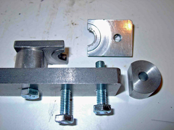
There is no need to dismantle the assembly any further.Next you need a bearing puller to remove the wheel bearing from the axle. This photo shows one I made from some scrap material. The two circular spacers are just a little thicker than the bearings, and the flattened sections simply ensure that the bearing will fit in between them while they still give a lot of support to the two puller jaws. Note how the puller jaws have a recess turned in them, they were turned as a single flat bar and then cut in half after the drilling was complete. This recess is to ensure that they only pull against the bearings inner section and do not touch the outer section. The bolts holding the puller together are all M6, and the two puller jaws are tapped M6 while the handle section is tapped M6 for the centre bolt and drilled 6mm diameter on the outer two holes.. |
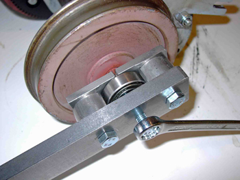 This
photo shows the bearing puller in use. The lose jaw from the
top
photo was bolted in place with the puller located around the axle, and
the centre bolt is tightened to slowly pull the bearing off the axle
end. This takes quite a lot of force, which is why the puller
is
so strongly constructed. This
photo shows the bearing puller in use. The lose jaw from the
top
photo was bolted in place with the puller located around the axle, and
the centre bolt is tightened to slowly pull the bearing off the axle
end. This takes quite a lot of force, which is why the puller
is
so strongly constructed. |
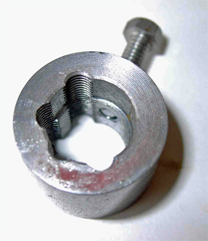 This
photo shows the sacrificial collar that is used when drilling the
axles. The two internal diameters are made to match the two
axle
diameters and the collar is the same thickness as the amount of axle
that protrudes from the wheels when they are in the correct position on
the axles. The bolt through the side of the collar was 4 BA. This
photo shows the sacrificial collar that is used when drilling the
axles. The two internal diameters are made to match the two
axle
diameters and the collar is the same thickness as the amount of axle
that protrudes from the wheels when they are in the correct position on
the axles. The bolt through the side of the collar was 4 BA.Before starting to drill any holes, first pull the wheel off the axle and clean away any oil or other debris. Then if necessary use some fine emery paper to clean and smooth the axle and wheel bore until the wheel slides nicely into its correct location on the axle. Next use some Loctite (type = Bearing Fit if possible) and use it to attach the wheel to the axle. Once the Loctite has hardened the drilling may begin. |
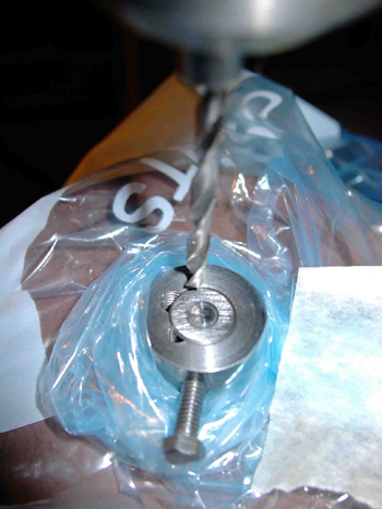 To protect the motor and gears
from swarf while drilling seal them inside two
freezer bags with small holes to let the axle stick out, then slide the
sacrificial collar into place and tighten the 4 BA bolt to lock it to
the axle. The motor and wheel assembly can now be supported
on a
couple of equally thick blocks on the pillar drill ready for drilling. To protect the motor and gears
from swarf while drilling seal them inside two
freezer bags with small holes to let the axle stick out, then slide the
sacrificial collar into place and tighten the 4 BA bolt to lock it to
the axle. The motor and wheel assembly can now be supported
on a
couple of equally thick blocks on the pillar drill ready for drilling.The photo shows the assembly on the drill table, and you can see that the end of the sacrificial collar lines up with the end of the axle. The chamfer on the end of the axle gives a good starting location for the twist drill so you have no need to centre punch anything. Now slowly and carefully drill using a 3.3 mm diameter drill so that half the hole is in the collar and half in the axle, and keep drilling until the hole is 27 mm deep. That's quite a long way, so just take your time and use lubricant very sparingly so as not to let it soak inside the freezer bags. Once drilled the hole is tapped full depth using a set of M4 taps. The sacrificial collar can then be removed and used when drilling the next wheel. |
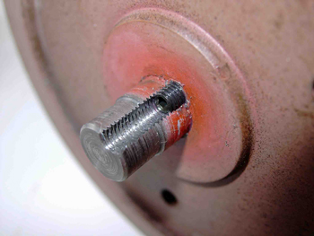 This
photo shows the wheel and axle after drilling and tapping M4.
The
wheel is locked to the axle using a M4 x 10 mm long Allen socket screw
which is also locked in place using Loctite (type = Screw Lock).
The screw should be wound almost fully into the hole so that
it
ends up clear of the step on the axle that acts as a locator for the
bearing. This
photo shows the wheel and axle after drilling and tapping M4.
The
wheel is locked to the axle using a M4 x 10 mm long Allen socket screw
which is also locked in place using Loctite (type = Screw Lock).
The screw should be wound almost fully into the hole so that
it
ends up clear of the step on the axle that acts as a locator for the
bearing.The bearing can now be pressed back into place using a suitable piece of tubing to ensure that pressure is only applied to the inner section of the bearing. Finally the Hercules may be reassembled. This modification ensures that the wheel cannot work lose on the axle, and the M4 screw also acts as a spline to transmit the torque between the axle and the wheel. |