 When
I ordered my Stafford from Station Road Steam in 2009 they refused to
fit a whistle of any kind to the locomotive so I had to fit my own, and
as you will see if you read the Stafford pages of this website getting
it to sound cleanly without spluttering to life as it expelled
condensed steam took me some time. When I traded in the
Stafford
for the Feldbahn I had expected SRS to be offering a whistle that
worked nicely and so I was quite disappointed to find that the whistle
valve they fitted constantly leaked and water ran freely from the
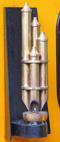
whistle down the boiler cladding. This looked unsightly but
the
worst part of it was that every time you sounded the lovely chime
whistle it spluttered into life imitating a decrepit fountain. You can
see the water collecting around the base of the whistle in this photo. When
I ordered my Stafford from Station Road Steam in 2009 they refused to
fit a whistle of any kind to the locomotive so I had to fit my own, and
as you will see if you read the Stafford pages of this website getting
it to sound cleanly without spluttering to life as it expelled
condensed steam took me some time. When I traded in the
Stafford
for the Feldbahn I had expected SRS to be offering a whistle that
worked nicely and so I was quite disappointed to find that the whistle
valve they fitted constantly leaked and water ran freely from the
whistle down the boiler cladding. This looked unsightly but
the
worst part of it was that every time you sounded the lovely chime
whistle it spluttered into life imitating a decrepit fountain. You can
see the water collecting around the base of the whistle in this photo.
I
lived with this for over a year while other more important tasks were
tackled but finally the time arrived to solve the problem.
The
root cause of the problem was simply that the commercial whistle valve
fitted by SRS always leaked slightly, and resultant slow flow of steam
condensed in the pipe leading to the whistle where it then dribbled
out. I had learnt from the Stafford that metal on metal valve
seats rarely seal 100% against steam at boiler pressure so what was
really needed was a whistle valve with a PTFE valve seat (or something
similar). As I couldn't find such a device for sale it seemed
that I had two alternatives; either to fit one of the R A Barker PTFE
seat whistles on the front of the cab and somehow rig up an operating
cord / chain or to design and make my own whistle valve. I
chose to design my own whistle valve for the simple reason that R A
Barker do not currently sell their excellent whistle valves with a
chime whistle fitted.
This page explains the reasons behind my design and gives details of
the whistle valve I created for the Feldbahn chime whistle.
|
 The
starting point was to adapt my O Ring clack valve design which has proven to be leak free
by adding an operating push rod to open the
valve (click
here
to see the relevant page on the Stafford section of this
website). Unfortunately although my new design worked perfectly using
compressed air the first time it was tested with steam the O Ring blew
off the shuttle and the whistle valve would no longer close. With
no other shut off valve available I had to endure the shriek of the
whistle for about 15 minutes while I dropped the fire and got rid of
the boiler pressure. After that I redesigned the valve to use a
PTFE valve without the O Ring and this seems to have solved all my
problems. Throughout the design of the new whistle valve
I had the following objectives in mind: The
starting point was to adapt my O Ring clack valve design which has proven to be leak free
by adding an operating push rod to open the
valve (click
here
to see the relevant page on the Stafford section of this
website). Unfortunately although my new design worked perfectly using
compressed air the first time it was tested with steam the O Ring blew
off the shuttle and the whistle valve would no longer close. With
no other shut off valve available I had to endure the shriek of the
whistle for about 15 minutes while I dropped the fire and got rid of
the boiler pressure. After that I redesigned the valve to use a
PTFE valve without the O Ring and this seems to have solved all my
problems. Throughout the design of the new whistle valve
I had the following objectives in mind:
1) There should be a minimum of high pressure joints or seals.
2) The valve seat should be easy to machine e.g. not
at the bottom of a deep hole.
3)
The cross sectional area of the steam passageways had to be
equal
to (or greater than) that in the original factory fitted steam valve.
4)
The valve should fit directly to the existing steam manifold
and
not obstruct the use of the new R A Barker steam valves.
5) The valve should be operated by a lever as opposed to any
form of chain.
The
existing dimensions of the clack valve O Ring initially set the basic
dimensions of the new whistle valve and thus the valve spring, while
the original whistle valve gave a minimum cross sectional
area
for the steam passageways of 13 sq mm. A suitable stainless
steel
compression spring was easily sourced from ENTEX Springs but I then
spent hours using my CAD program sketching many potential valve designs
before I settled on the design shown here.
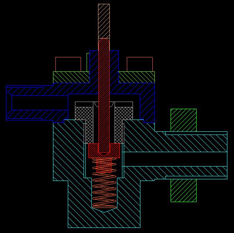
The drawing
reproduced from my CAD program shows the cross section through the
middle of the whistle valve. The main body of the whistle
valve
is shown in light blue and the spigot on the right screws straight into
the Feldbahn's steam manifold (1/4" BSP thread) and is locked in place
by the nut shown in green. Steam enters via the offset steam
passage to reach the valve chamber which contains the spring (light
brown) and the PTFE valve (red). The PTFE valve seats
against its valve face on the bottom
of the removable threaded bush (white). Experience of my O
Ring
clack valves had taught me that I could machine such a bush
and
main body face to be steam tight against the full boiler pressure.
The valve top cap (dark blue) is bolted onto the main valve
body
using M4 socket cap head screws, but being on the outlet side of the
valve this joint does not need to be so steam tight as the main valve
body components. Steam exits the valve top cap via the spigot on
the top left which is threaded 3/8"x32 to accept a normal 1/4" diameter
pipe nipple.
|
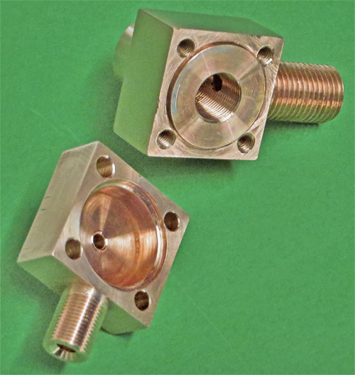 This
photo shows the whistle valve body (top) and valve cap (bottom)
machined from 1 1/4" square phosphor bronze bar. To save on metal they could
probably have been manufactured using several parts silver soldered
together but I had a suitable piece of bar so the parts were turned
using the four jaw chuck on my lathe. This
photo shows the whistle valve body (top) and valve cap (bottom)
machined from 1 1/4" square phosphor bronze bar. To save on metal they could
probably have been manufactured using several parts silver soldered
together but I had a suitable piece of bar so the parts were turned
using the four jaw chuck on my lathe.
Valve Body.
The
input spigot was the first part to be machined and then threaded 1/4"
BSP. Since the spigot is well offset from the centre of the bar
this operation has the most out of balance mass spinning on the lathe,
but by using a low spindle speed with shallow cuts at a low rate I
managed it without resorting to any counterbalance weights. The
part then needed to be offset again in the chuck to drill the inlet
steam port.
The face opposite the inlet spigot was then faced back to create the correct width of the valve body.
Turning
the part again in the chuck allowed the circular lower body (at the
back in the photo) of the valve to be turned before further
repositioning in the chuck allowed the remaining two sides to be faced
back. Obviously all of these operations had to end up with the
various faces correctly positioned with reference to the centre line of
the inlet spigot.
Finally the top face of the valve body was faced
off at +1mm from the designed body thickness, the various diameters
were drilled and tapped, and only then was the top face finally faced
to the correct thickness and the set back area turned to create the
raised boss that would locate the valve cap.
The four tapped holes that retain the cap to the body would be drilled later using the cap as a drilling guide.
Valve Cap.
This
was machined in a similar fashion to the valve body, spigot first with
its 3/8"x32 thread and outlet port and pipe nipple seat. Then the
sides were faced followed by the turning of the boss on the face
hidden from view in the photo. Finally the mating face of the
valve cap was faced and bored to create the main cavity. The
larger recessed diameter was machined to be a close fit over the raised
boss on the valve body, and the spindle hole was drilled through from
the cavity side to ensure concentricity. This hole needs to be a
close sliding fit for the valve operating rod so that the rod can slide
easily, but with the minimum of clearance to reduce the amount of steam
that can escape when the whistle valve is operated.
A simple jig was then
made that located over the boss on the top of the valve cap to allow
the four holes to be drilled through the cap at the tapping drill size
for the M4 bolts. The cap was then clamped to the valve body
(ensuring that it was correctly aligned) and the holes frilled down
into the valve body.
The body holes could then be tapped M4 while
the cap holes were opened out to clear the M4 stainless steel socket
cap screws that would hold the cap to the body.
Making these two parts took the best part of a day of lathe work.
|
 The
1/4" BSP locknut was machined from a scrap piece of phosphor bronze
hexagon bar, remembering to relieve the hexagonal section on the mating
face so that the points of the hexagon would not scratch paint off the
steam manifold as the nut was tightened. You can just see the
relieved section in the photo. The
1/4" BSP locknut was machined from a scrap piece of phosphor bronze
hexagon bar, remembering to relieve the hexagonal section on the mating
face so that the points of the hexagon would not scratch paint off the
steam manifold as the nut was tightened. You can just see the
relieved section in the photo.
The removable threaded bush
that has the valve seat on its lower face was also machined from
phosphor bronze hexagon. This part looks easy to make but it
needs care to ensure that the valve face is really flat and without
burrs around the steam passage hole. Basically drill the steam
passage before facing the valve seat. The mating face between the
bush and valve body also needs to be really smooth with the thread
correctly relieved to ensure that the bush screws fully home into the
valve body where it will create a steam tight seal. Some Copper
Ease grease applied sparingly to the thread will help with the seal and
prevent the bush seizing into the body. You can just make out the
residue of the Copper Ease along the edges of the bush hexagons in this
photo.
The half diameter holes in the top face of the bush
are there to provide additional steam passage space between the bush
and the valve cap. These were drilled through the hexagon bar
before the face was turned to create the correct thickness.
|
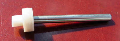 This
photo shows the PTFE valve and the operating push rod. PTFE isn't
my favourite material to turn but the part didn't give me any real
problems. A 3mm diameter hole for the operating rod was drilled
3mm deep into the seating face before that face was finally faced off
by another millimetre. As before, making the part this way
results in less chance of burrs on the valve seating face than if the
hole was drilled after the face had been turned. The spigot on
the left of the photo was then formed using the parting tool. It
needs to be a slightly loose fit inside the coil spring. Finally
the valve was parted off and the finished valve face was inspected
using a magnifying glass. As I couldn't see any surface scratches
or imperfections I decided that it would probably be good enough to
provide a steam tight seal when the valve was closed. This
photo shows the PTFE valve and the operating push rod. PTFE isn't
my favourite material to turn but the part didn't give me any real
problems. A 3mm diameter hole for the operating rod was drilled
3mm deep into the seating face before that face was finally faced off
by another millimetre. As before, making the part this way
results in less chance of burrs on the valve seating face than if the
hole was drilled after the face had been turned. The spigot on
the left of the photo was then formed using the parting tool. It
needs to be a slightly loose fit inside the coil spring. Finally
the valve was parted off and the finished valve face was inspected
using a magnifying glass. As I couldn't see any surface scratches
or imperfections I decided that it would probably be good enough to
provide a steam tight seal when the valve was closed.
The
operating rod was simply a length of 3mm diameter stainless steel with
its ends faced off. As it needs to fit between the closed PTFE
valve and the valve lever with only a small amount of clearance I found
it easier to make this part after everything else had been completed.
|
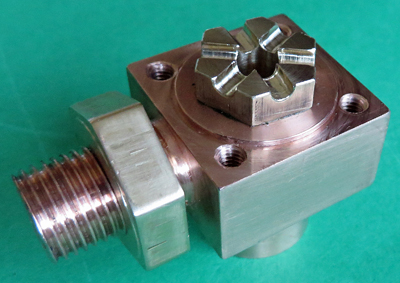
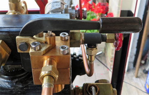 Here
is the finished whistle valve fitted to my Feldbahn. The
operating lever was cut from 3mm thick mild steel and has a varnished
wooden knob on the end. Note how the lever extends down below the
pivot on the left to act as a stop to prevent the lever from lifting up
further than necessary. The valve operating rod described in the
section above ends up with about 0.5mm of clearance between it and
the operating lever when the lever is fully "up". Here
is the finished whistle valve fitted to my Feldbahn. The
operating lever was cut from 3mm thick mild steel and has a varnished
wooden knob on the end. Note how the lever extends down below the
pivot on the left to act as a stop to prevent the lever from lifting up
further than necessary. The valve operating rod described in the
section above ends up with about 0.5mm of clearance between it and
the operating lever when the lever is fully "up".
The lever
pivot bracket was silver soldered from 3mm thick brass and the 4ba
pivot bolt is threaded into the pivot bracket. On the hidden
side, a 4ba Nyloc nut secures the lever and with careful adjustment
stops the lever from flopping about sideways to keep it centred over
the operating rod.
So
far the whistle valve has been working
well and no water has been seen weeping out of the whistle so I hope
that the leaky whistle valve problem has been solved. I have
deliberately avoided putting the CAD drawings on the website because so
far the valve is an experimental part, but if you would like a copy of
the CAD drawings then please contact me via the link at the top of the
page. |