 |
 |
The Walter S Winans, a radio controlled model
submarine
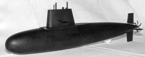 When I built the Walter S
Winans in 1981 it was designed to have a main ballast tank that would
enable it to run fully surfaced or to "flood down" to retain only the
absolute minimum of buoyancy and then "dive" using forward momentum and
its elevator controls. The big advantage of this method is
that
if anything goes wrong when dived the model will most likely float back
to the surface, and it can never run out of compressed air to blow
ballast tanks (as could happen with models using compressed air to
operate their ballast tanks). Unfortunately this
configuration
resulted in some "snide" comments from members of the Association of
Model Submarines who while acknowledging the capabilities of the model
constantly told me that it wasn't a "real" model submarine because it
couldn't dive vertically (propulsion motors stopped) by flooding its
ballast tanks. The result was that I quickly altered the
ballast
tank system so that it could fully control two ballast tanks to
"dive vertically", albeit without using compressed air. When I built the Walter S
Winans in 1981 it was designed to have a main ballast tank that would
enable it to run fully surfaced or to "flood down" to retain only the
absolute minimum of buoyancy and then "dive" using forward momentum and
its elevator controls. The big advantage of this method is
that
if anything goes wrong when dived the model will most likely float back
to the surface, and it can never run out of compressed air to blow
ballast tanks (as could happen with models using compressed air to
operate their ballast tanks). Unfortunately this
configuration
resulted in some "snide" comments from members of the Association of
Model Submarines who while acknowledging the capabilities of the model
constantly told me that it wasn't a "real" model submarine because it
couldn't dive vertically (propulsion motors stopped) by flooding its
ballast tanks. The result was that I quickly altered the
ballast
tank system so that it could fully control two ballast tanks to
"dive vertically", albeit without using compressed air.In that format the model quickly attracted the attention of John Cundell of the Model Boats magazine who asked me to write a series of articles about the model to accompany their marketing of hull mouldings to let people build their own replica of the model. I did complete some drawings, and took some suitable explanatory photos, but when John told me that they planned to use plastic extrusions for the hull forms (I had used fibreglass hull mouldings) I decided that the new construction method would be too different to my original to be easy to write about without building my own "new" version. The end result was that the drawings and articles were not published and when I sold the model a few years later it seemed as if the full information about the model had been lost. However in 2012 I found the plans in the bottom of an old holdall, and this page is the result. If you are interested in building a replica of the model, or just want to see some higher resolution copies of the photos or the full size plans, then please Right Click here to download the plans and photos in ZIP file format and then save the file on your computer. |
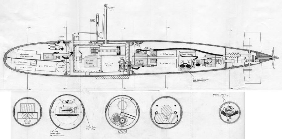 |
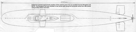 The
main hull of the model was constructed of fibreglass mouldings with the
split along the horizontal centre line using moulds made for me by my
friend
Paul South of the Hanwell & District Model Boat Club.
Once
trimmed along the edges to fit together correctly they were simply
taped together using waterproof tape and put in the bath to establish
exactly where the centre of buoyancy was. This position
needed to
be in the centre of the ballast tank, and once found everything else
had to fit around it. At the same time I was able to measure
how
much ballast was needed to go from surfaced to neutral buoyancy, which
determined the size of the ballast tank. My plan was to fit
water
tight bulkheads to
either side of the ballast tank, with another bulkhead towards the rear
of the hull to leave a free flooding space at the rear of the hull for
the control linkages and the propeller drive gearbox. The
main hull of the model was constructed of fibreglass mouldings with the
split along the horizontal centre line using moulds made for me by my
friend
Paul South of the Hanwell & District Model Boat Club.
Once
trimmed along the edges to fit together correctly they were simply
taped together using waterproof tape and put in the bath to establish
exactly where the centre of buoyancy was. This position
needed to
be in the centre of the ballast tank, and once found everything else
had to fit around it. At the same time I was able to measure
how
much ballast was needed to go from surfaced to neutral buoyancy, which
determined the size of the ballast tank. My plan was to fit
water
tight bulkheads to
either side of the ballast tank, with another bulkhead towards the rear
of the hull to leave a free flooding space at the rear of the hull for
the control linkages and the propeller drive gearbox.The rudders and elevators were to be fitted such that their shafts were "one behind the other" and would not therefore need complicated "cranking" to pass each other, and by fitting a 2-1 reduction gearbox on the propeller side of these links the propeller shaft also missed them on its way forwards to the drive motor. At this stage of the design / build that was about all I knew about my intended model, everything else relied on my convictions that a model submarine of this size (690mm long) could actually be built at a time when every other model submarine that I knew about with its capabilities was well over 2 metres long. |
 Perhaps
one of the most important items of equipment for this model was the
(then new) JR series of radio control which used FM modulation to carry
the control signals. If you have ever listened to an old AM
(amplitude modulated) radio you will almost certainly have heard how
much "background noise" (interference) it has when compared to newer FM
(frequency modulated) radio channels. The same principle
applied
to model submarines, with AM systems being more prone to control
interference than FM systems. Since every electric motor in
the
model submarine (drive, pumps, servos etc.) and many metal to metal
moving parts / linkages can all create electrical interference on an AM
system the (then) new FM system would allow the model to dive much
deeper before its internally generated interference would upset the
control system of the model. The use of the 6 channel JR
radio
control system and its servos thus defined another set of component
parameters. While on the topic of electrical interference I
should also point out that every electric motor in the model was fitted
with interference suppression capacitors (each brush terminal to the
motors casing) and wires then connected every motor case (and many
other "moving" metal components) to the metal propeller shaft tube to
effectively "earth out" any potential interference. Perhaps
one of the most important items of equipment for this model was the
(then new) JR series of radio control which used FM modulation to carry
the control signals. If you have ever listened to an old AM
(amplitude modulated) radio you will almost certainly have heard how
much "background noise" (interference) it has when compared to newer FM
(frequency modulated) radio channels. The same principle
applied
to model submarines, with AM systems being more prone to control
interference than FM systems. Since every electric motor in
the
model submarine (drive, pumps, servos etc.) and many metal to metal
moving parts / linkages can all create electrical interference on an AM
system the (then) new FM system would allow the model to dive much
deeper before its internally generated interference would upset the
control system of the model. The use of the 6 channel JR
radio
control system and its servos thus defined another set of component
parameters. While on the topic of electrical interference I
should also point out that every electric motor in the model was fitted
with interference suppression capacitors (each brush terminal to the
motors casing) and wires then connected every motor case (and many
other "moving" metal components) to the metal propeller shaft tube to
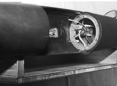
effectively "earth out" any potential interference.The photo on the left shows the free flooding space at the rear of the model and it is just possible to see the propeller shaft reduction gear as well as the elevator control crank. The rear bulkhead was made from 16swg brass sheet so that many parts could be soldered to it (propeller and control shafts, sub-frame mounts, grease points etc.) before it was fibreglassed into position. The propeller was based on the then new American design of slow rotating, multi bladed propellers, with scimitar shaped blades; but of course I had to make it myself. The brass cone for its centre was turned on my Unimat SL lathe, and two roles of 1/16" diameter holes were drilled into it (using the dividing head and vertical pillar) to locate two small lugs on the bottom of each blade. The blades could thus be "force fitted" into the centre boss and silver soldered into place. The finished propeller was mounted onto a 6BA thread on the propeller shaft and once the required shaft end float was set the propeller was locked in place by a 6BA Allen head grub screw. There are drawings for the propeller in the downloadable drawing pack (see the "link" near the top of the page). |
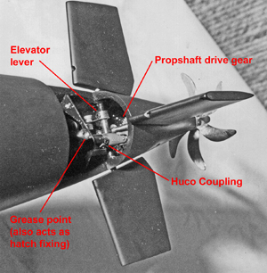
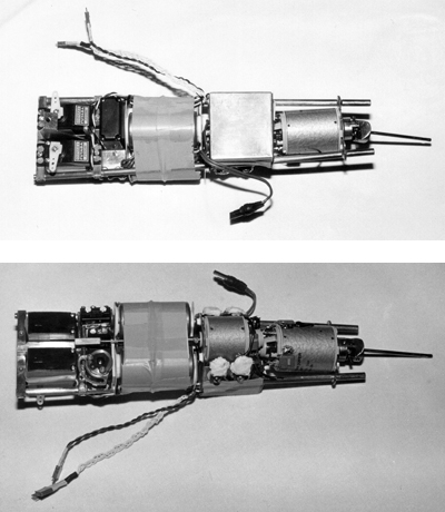 The
two photos on the right show the rear compartment module (the top photo
shows the module top view and the bottom photo the view from
underneath). You will be able to see much more if you look at
the
high resolution photos available in the "download" ZIP file. The
two photos on the right show the rear compartment module (the top photo
shows the module top view and the bottom photo the view from
underneath). You will be able to see much more if you look at
the
high resolution photos available in the "download" ZIP file.The entire contents of the rear water tight compartment of the model were mounted onto a removable brass frame, the rear of which located into two tapered sockets on the inside of the rear brass bulkhead while the front was held in place by a single mounting bolt. Using the tapered mounting sockets meant that although invisible, it was still easy to slide the assembly into position inside the hull. The bigger problem was to align the propshaft with the propeller shaft tube when the assembly was being fitted, but this was resolved by drilling a small hole in outermost end of the propshaft. A length of Piano Wire could then be slid through the hull mounted propeller shaft tube (via a small hole in the hull) such that it could be located into the hole in the assemblies propshaft while still visible in the centre (ballast tank) area of the model. As the assembly was slid into the hull the propeller shaft was automatically guided into place by the Piano Wire until the propshaft engaged into a tapered leading edge hole of the propeller shaft tube. A single link Huco universal coupling connected the propeller shaft to the propeller gear box shaft. Inside the model there was not enough length to fit a double link Huco universal coupling, so the coupling just visible at the extreme right of the photos was fabricated from brass. It looks like a very short, but large diameter, single link universal joint; but the yoke pins are much elongated and allowed to slide in the outer bodies of the joint. The result is a universal joint that can cater for both angular and linear offset between the input and output shafts (which was essential with this installation). The drive motor shown was the original Monoperm Super Special (6V being run on 7.2V from the 1.8Ah Nicads) but this was later replaced with a similar lower power Monoperm motor to that on its left in the photos which drove the main ballast pump. The reason for reducing the motor power was that the original model was simply too fast at top speed, and I also needed the weight reduction when I retro fitted the "trim" ballast tank for vertical diving. The main ballast tank pump was a "gear" pump and it was mounted on the rear compartment removable front pressure bulkhead. As a result it needed to be connected to the pump motor via a "slide fit joint" (so that it would slide into place as the bulkhead was screwed into place) and it also needed some form of flexible drive to accommodate any misalignment with respect to the motor. Once again there was no room for any conventional universal joint, so in this case a short length of square section tubing (you can just see it near the left of the lower photo) was connected to the pump motor using a length of Piano Wire as a flexible coupling. The ballast pump shaft had a square end that simply slid into the shaft tube as the bulkhead was pushed into place. Also visible in the photo are the two servos for the rudder and elevator controls, and sandwiched in between them (with the complicated looking servo output linkage in the lower photo) is the servo that operated the two micro switches that controlled which way the ballast tank pump operated. Unfortunately I can't locate any photos of the ballast tank gear pump, but the main sectional drawings of the model (see download "link" near page top) show how it was built. The big advantage of using a gear pump to operate the ballast tank is that it directly pumps the water into, and out of, the main ballast tank. As later shown when the model was operated under ice, the pump can even "draw a vacuum" inside the main ballast tank to let the model rise even when the ballast tanks air inlet is closed because the snorkel is submerged (or the model is under the ice). The final items visible in the photos are the custom built drive motor speed controller, the obvious box in the top photo, and some of the main 7.2V 1.8Ah Nicad batteries (the rest were in the front compartment). Those of you who know the Monoperm series of motors may also notice that in the lower of the photos the motor end caps over the commutators have been removed (more easily seen in the high resolution downloadable photos). This had to be done to get the two motors to overlap each other because there simply wasn't enough space in the model to fit the motors in the form that the manufacturer made them ! |
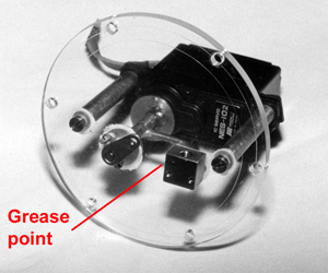  These two photos show the
operating system for the snorkel that was used to "vent" the main
ballast tank. These two photos show the
operating system for the snorkel that was used to "vent" the main
ballast tank.The left hand photo shows the removable water tight bulkhead that fitted to a Perspex ring fibreglassed into the hull at the front of the ballast tank bay. The photo shows how the snorkel servo was mounted to the bulkhead and the control brought out of the bay via a grease filled tube. All the "moving" propshaft and rotating control links used identical 4BA threaded grease nipples to that shown in the photo, and if freshly packed with grease before a run they never admitted any water even when dived to 16 feet. The servo raised or lowered the snorkel (its "dustbin" shaped top cap is not fitted in this photo for some long forgotten reason) via the linkage shown on the right which was all hidden inside the conning tower (or Sail as the Americans call it). The ballast tank vent tube was sleeved by the snorkel tube (two close fitting lengths of K&S brass tubing) so that the ballast tank vent was sealed when the snorkel was in the down position (or opened when the snorkel was raised). This allowed the ballast tank pump to partially empty the main ballast tank by creating a vacuum inside it when the snorkel was down (vent closed) which was useful for more rapid surfacing manoeuvres or under ice operation. One of my useful "tricks" is also shown in the photo on the snorkel linkages (better seen in the downloadable high resolution photo) and that is how to create a very low backlash clevis joint. The technique works at any scale, but this linkage used 8BA sizes. The brass push rods have 8BA brass nuts silver soldered to their ends, and a similar nut is soldered to the lever (or the lever may be tapped if thick enough). A suitable brass screw is then screwed in from either side of the link (as is most suitable) and as it emerges from the first item it is screwed into the second. Once fully tightened onto whichever part is under the screw head you have a very low backlash "clevis" joint which won't fall apart. The method is cheap, quick and easy to make, very strong, and if you cut the moving part thread by deliberately moving the handle end of the tap in a circular motion (to widen the thread diameter at either end of the through hole) you can even get a low backlash joint that permits movement in two axes (albeit somewhat limited in one). The slightly shorter tube in the right hand photo has the hull pressurising bicycle valve fitted into its top. By using three strokes of a bicycle pump before the model was launched it ensured that if a leak did start to occur it would be air coming out of (rather than water going into) the model which was always a better option, and had the added advantage of showing bubbles rising through the water to indicate any potential problems (although thankfully none ever occurred). |
 This
photo shows the forward water tight bulkhead mounting ring, made from
1/4 thick Perspex and sealed into the hull using glassfibre.
The
forward compartment held the radio control receiver, the snorkel servo,
the radio batteries, some drive batteries, and the master On/Off
switch. The switch was accessed through a small
screw fitted
hatch located just in front of the conning tower. This hatch
was
actually made from the cylinder head and top section of the cylinder
barrel of a COX 049 glow plug engine (I once bought several for next to
nothing from a model shop that was closing down) which being precision
engineered components gave a very good water tight seal when screwed
shut. This
photo shows the forward water tight bulkhead mounting ring, made from
1/4 thick Perspex and sealed into the hull using glassfibre.
The
forward compartment held the radio control receiver, the snorkel servo,
the radio batteries, some drive batteries, and the master On/Off
switch. The switch was accessed through a small
screw fitted
hatch located just in front of the conning tower. This hatch
was
actually made from the cylinder head and top section of the cylinder
barrel of a COX 049 glow plug engine (I once bought several for next to
nothing from a model shop that was closing down) which being precision
engineered components gave a very good water tight seal when screwed
shut.The various plugs and sockets on the wires in the photo connected the front compartment module to the submarine wiring. The radio receiver aerial was actually moulded into the fibreglass hull of the model so that it could never make electrical contact with the water (an absolute essential if the radio is to work when dived). The other wires ran through two brass eliptical section cable ducts (K&S tubing) moulded into either side of the hull that linked the front and rear compartments. The two Perspex water tight bulkheads were simply given a smear of Vaseline and then fixed in place with six off 6BA brass screws through each bulkhead into tapped holes in the bulkhead rings. This method of sealing the hatches never leaked, and despite some concern about the strength of 1/8" Perspex when drilled in so many places the bulkheads didn't fail even when dived to a depth of 16 feet. |
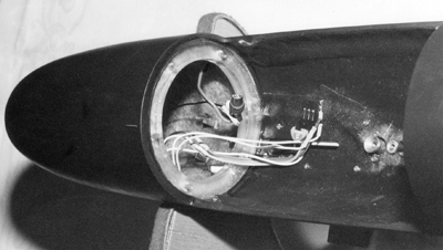
 This
photo shows the view into the rear compartment of the submarine with
the internal module removed. As with the front compartment
there
were several connectors to be fitted together when the module was
fitted into the hull, but this section also had the two clevis links
for the Rudder and Elevator that had to be connected to the servos (a
fiddly affair, normally involving the use of a watchmakers screwdriver
and a pair of tweezers). These two controls used model
aircraft
style nylon "rod and tube" flexible linkages with small rubber bellows
on their outer ends to provide water tight seals. This
photo shows the view into the rear compartment of the submarine with
the internal module removed. As with the front compartment
there
were several connectors to be fitted together when the module was
fitted into the hull, but this section also had the two clevis links
for the Rudder and Elevator that had to be connected to the servos (a
fiddly affair, normally involving the use of a watchmakers screwdriver
and a pair of tweezers). These two controls used model
aircraft
style nylon "rod and tube" flexible linkages with small rubber bellows
on their outer ends to provide water tight seals.The space in between the two watertight bulkheads held the main and trim ballast tanks as shown on the main cross sectional drawings, but unfortunately I cannot now find any photos of this assembly. The lower rear section of the main ballast tank held the gear pump, and it connected to the drive shaft coming through the rear water tight bulkhead by a simple "tongue and slot" coupling. This pump used two of the plastic gears from a Hectoperm Pile Gearbox which had oversize shaft holes in them so that they could "float" on their shafts with the drive gear being driven by a cross pin in the drive shaft. This allowed the gears to be a very accurate fit in their chambers even if I hadn't got the shafts exactly in the centre of the casings. In order to work efficiently a gear pump needs the two gears to be very close fits into their chambers, both in thickness and on their diameters. So each gear was polished on 1200 gauge Wet&Dry paper to get the desired thickness (with flat faces), and their chambers and cover plates were turned from Perspex rod on the Unimat SL lathe. Each chamber, with its cover plate attached by 8BA brass screws, then had the correct amount milled off (again using the Unimat SL) so that when the two chambers were pushed together the gears were in perfect mesh. The two half chambers then had their inlet and outlet ports cut before they were glued together using Chloroform as a solvent "glue". Back in the 70's and 80's Chloroform was reasonably easy to obtain and it was the perfect liquid glue for Perspex as well as Polystyrene or ABS. The upper section of the main ballast tank held the plastic barrel of a medical syringe which acted as the trim ballast tank. When the syringe plunger was in mid position, and the main ballast tank was full of water, the submarine's lead ballast was set to achieve neutral buoyancy. As a result as a servo pushed the syringe plunger back and forwards in the barrel the ballast tank would hold either more of less water to give + or - about 1 ounce of ballast from neutral which was sufficient to give a decent rate of vertical dive or ascent. The syringe servo was mounted in a watertight section formed from concentric plastic tubes (rolled from polystyrene sheet) attached to the front of the main ballast tank. The syringe servo was a heavily modified aircraft undercarriage servo (the only type with enough power to move the syringe plunger in its barrel) with micro switches used to limit the servos travel as it operated the syringe plunger via a rack and pinion system fitted to the servo and syringe plunger shaft. The watertight seal for this servo chamber was the lowest tech' bit of the submarine, simply using Sleek waterproof surgical tape to cover the seam of the overlapping plastic tube sections. I don't think that Sleek is available anymore, but it was a wonder material in its day being thin, strong, stretchy, very sticky, totally waterproof, and easily removable after use. |
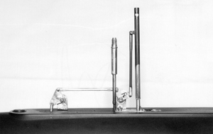
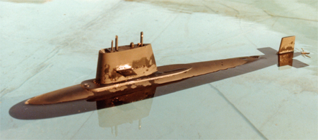
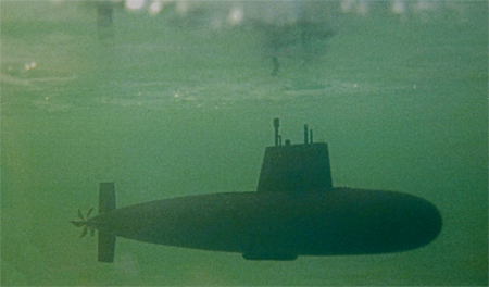 Operationally
the model exceeded my expectations for it. It looked sleek
and
modern, dived superbly well, its top speed once dived was very
fast (even with the later reduction in drive motor size), and it would
normally run for between 2 and 2 1/2 hours after charging the
batteries. During its life I operated it in all sorts of
situations ranging from the idyllic waters of swimming pools, through
various test tanks, to the dirty waters of canals and a Dutch polder;
and its behaviour (at sensible speeds) was consistent enough that it
could be operated dived whilst invisible in murky water and still be
surfaced pretty much exactly where I expected it to be. Operationally
the model exceeded my expectations for it. It looked sleek
and
modern, dived superbly well, its top speed once dived was very
fast (even with the later reduction in drive motor size), and it would
normally run for between 2 and 2 1/2 hours after charging the
batteries. During its life I operated it in all sorts of
situations ranging from the idyllic waters of swimming pools, through
various test tanks, to the dirty waters of canals and a Dutch polder;
and its behaviour (at sensible speeds) was consistent enough that it
could be operated dived whilst invisible in murky water and still be
surfaced pretty much exactly where I expected it to be.Its only negative aspect was its behaviour at high speeds where it taught me a lot about submarine hydrodynamics. If you turn a tight fast corner with a model warship it will normally just roll and lean out of the turn. A submarine, due to the relationship of its centre of buoyancy to its centre of mass, will lean into the turn so that it appears to bank rather like an aircraft. However the conning tower (Sail) also acts like a wing and during the turn it develops "lift" to exaggerate the angle of roll to such an extent that at high speeds (and in deep water) the model would actually go into a rolling spiral dive. This meant that at high speeds the rudder had to be used quite carefully and turns kept to a large radius. This photo shows the model in the process of diving vertically again after it had surfaced through the ice on the model boat pond at the London Model Engineering Exhibition. If you look closely at this photo you can see the hole left in the ice by the conning tower and the cracked ice extending from the hole where it had been broken and lifted by the hull of the surfacing submarine. (For those of you who arrived directly on this page from your browser the "back to" links at the top and bottom of this page will take you back to my main model page where you will find a photo of this model surfaced through the ice.) It turned out that this model was the last radio controlled model I was ever to build, except for a model Land Rover built for charity fund raising, click here to see it. Quite simply I didn't know what to build next. A scale model of a British B Class submarine was drawn up, but that would have been more of the same. To answer yet more criticism from the Association of Model Submariners "you must use compressed air to blow tanks" (Why ?) and "you can't use electric motors for surface propulsion" (Can you build a miniature nuclear reactor and steam turbine ?) I did start to experiment with trying to build a K Class submarine with a flash steam boiler, but it was really a step too far and the cost would have been ludicrous. So eventually in 1985 I sold this model to a friend for £650 which covered the cost of its parts and materials and moved on to building full sized Off Road 4x4s for competitions. |
 There
isn't much more that I can
write about the Walter S Winans, and I'm sure that technology will have
moved on so far in the last 30 years that anyone using the downloadable
plans (see the "link" near the top of the page) will easily find modern
RC systems and servos to do the required tasks. I'm not so
sure about
electric motors though as the Marx 'Perm range of motors were absolute
gems for model making even if rather expensive then, and ridiculously
so now when I recently found some for sale on the Internet.
However, beyond the
basic components it's all about designing and fabricating your own
custom parts. My drawings and this text will probably give
you some ideas, but whatever
you build will be your own unique design. Good luck if you
choose to
recreate this model. It gave me a huge amount of pleasure to
own and
operate, and even got itself onto the BBC TV when it was used to dive
in a tank of very large Pike to compare submarines with fish. There
isn't much more that I can
write about the Walter S Winans, and I'm sure that technology will have
moved on so far in the last 30 years that anyone using the downloadable
plans (see the "link" near the top of the page) will easily find modern
RC systems and servos to do the required tasks. I'm not so
sure about
electric motors though as the Marx 'Perm range of motors were absolute
gems for model making even if rather expensive then, and ridiculously
so now when I recently found some for sale on the Internet.
However, beyond the
basic components it's all about designing and fabricating your own
custom parts. My drawings and this text will probably give
you some ideas, but whatever
you build will be your own unique design. Good luck if you
choose to
recreate this model. It gave me a huge amount of pleasure to
own and
operate, and even got itself onto the BBC TV when it was used to dive
in a tank of very large Pike to compare submarines with fish.If you have any questions, or comments, about the model please click here to open my website contact page. |
 |