 |
 |
Special Effects
| This
page relates to a rather
special group of radio controlled models (and modellers) that existed
in the mid 1970's, a time when special effects for use on theatrical
stages were easy to purchase and the world was somewhat more relaxed
than it is today. I really wouldn't advocate anyone
replicating
these models and their capabilities today, although there are now
probably much better (and safer) ways of creating similar effects.
As the saying goes "Don't try this at home". Unfortunately the cameras (and bathroom developing / printing lab) available to us in the 70's didn't produce the quality photos we are now used to, so I can only apologise for the rather poor quality of the action photos on this page. |
| Convoy Attack Display |
 The
first demonstration that my friends and I created involved radio
controlled models of a German U-Boat, a Flower Class Corvette, and a
couple of merchant vessels representing part of a World war II convoy.
The display was best
run in clear water so that the submarine was visible to the spectators,
but its builder and operator (Steve Kirby) was quite adept at
controlling it under the "dirty"
water of normal lakes and gravel pits. The various
pyrotechnic
effects on the models worked equally well in any kind of water !
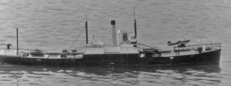
The model shown here is my Camship (Catapult Armed Merchant
Ship)
which had to take the brunt of the special effects used to simulate the
attacks on the convoy. The
first demonstration that my friends and I created involved radio
controlled models of a German U-Boat, a Flower Class Corvette, and a
couple of merchant vessels representing part of a World war II convoy.
The display was best
run in clear water so that the submarine was visible to the spectators,
but its builder and operator (Steve Kirby) was quite adept at
controlling it under the "dirty"
water of normal lakes and gravel pits. The various
pyrotechnic
effects on the models worked equally well in any kind of water !
The model shown here is my Camship (Catapult Armed Merchant
Ship)
which had to take the brunt of the special effects used to simulate the
attacks on the convoy.The model was about 2 metres in length and was built to be as watertight as a submarine. When the display commenced it would be used to tow another similar sized model, which early on in the display would be sunk by bombs from an unseen German aircraft. The underwater tow line would then be dropped and the model Hurricane aircraft was launched into the air (amid a pall of smoke simulating the launcher sled rockets). As the Hurricane was made of painted Balsa wood it never really appreciated its eventual soakings from its landing in the water, so the flight was always somewhat unpredictable. The only consistent aspect of its flight was that it would always perform a full loop immediately after takeoff as a result of the very high launching speed needed to make it fly any distance. Analysis of the frames from a long lost 8mm home movie showed that the elastic powered catapult accelerated the Hurricane to over 60 mph ! |
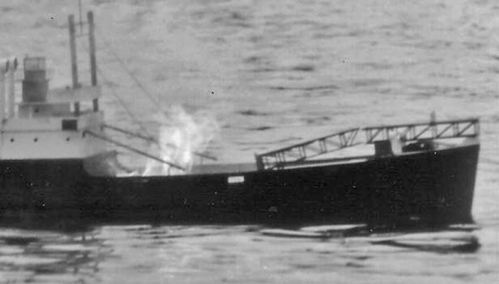 The
next photo shows the Camship after it had been torpedoed by the
submarine. A very small amount of Flash Powder had been
exploded
against the hull to simulate the torpedo hit (I had tried all sorts of
spring operated pumps to no avail), another spring operated ram had
thrown the forward hatch cargo into the water and allowed the catapult
ramp to collapse, and a small fire was ignited in the hull.
At
the same time a large valve had been opened to allow the forward hold
to flood, which after a minute or so had the ship in a very nose down
trim. The
next photo shows the Camship after it had been torpedoed by the
submarine. A very small amount of Flash Powder had been
exploded
against the hull to simulate the torpedo hit (I had tried all sorts of
spring operated pumps to no avail), another spring operated ram had
thrown the forward hatch cargo into the water and allowed the catapult
ramp to collapse, and a small fire was ignited in the hull.
At
the same time a large valve had been opened to allow the forward hold
to flood, which after a minute or so had the ship in a very nose down
trim.Then came the sneaky bit. The entire centre section of the ship was watertight up to the uppermost deck level, and a powerful winch then lifted all the lead ballast from the keel up to the top right of the ship which caused it to capsize and roll over, with the funnel and deck cargo falling into the water. After the display was over the lead ballast could be winched back to right the ship, so that it could be driven back to the shore (but we still had to use a rubber dingy to retrieve all the cargo and fittings lost overboard.). |
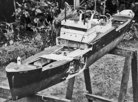 This
final photo shows what happened when the torpedo charge had slightly
the wrong affect. The charge had been made to the same size
as in
all the other displays so it was expected to have had the same effect
as before, but for whatever reason the result was rather more
spectacular than desired. Remarkably the ballast winch still
worked to let the model capsize and finish the display, but the Camship
never sailed again. The fibreglass hull was salvaged and
rebuilt
into a whale factory ship (see the main model boat page) that was never
finished for the simple reason that at over 15 feet in length it was
simply too big for many of the lakes we operated on. This
final photo shows what happened when the torpedo charge had slightly
the wrong affect. The charge had been made to the same size
as in
all the other displays so it was expected to have had the same effect
as before, but for whatever reason the result was rather more
spectacular than desired. Remarkably the ballast winch still
worked to let the model capsize and finish the display, but the Camship
never sailed again. The fibreglass hull was salvaged and
rebuilt
into a whale factory ship (see the main model boat page) that was never
finished for the simple reason that at over 15 feet in length it was
simply too big for many of the lakes we operated on.For a while the group tried its hand at displays without the pyrotechnics, in particular the whale hunting scenario, but within a year the next spectacle was created. |
Commando Raid Display |
| At its peak this display created by three friends and I involved 1/25th scale models of three landing craft and seven assorted tanks and other vehicles, together with a large number of special effects to create a show lasting about ten minutes. We even had our own special effects laden beach 8 feet wide and 12 feet deep which had to be transported in sections on the roof of our cars to whatever pond we were operating on. |
 The
main landing craft used for the display was a 6 foot long model of a
LCT (Landing Craft Tank) which carried a varied assortment of vehicles
onto the beach for a commando style raid, but as the models used
represented vehicles from widely different eras the raid could never be
called a representation of a specific event. It was just good
old
fashioned special effects to make a good show. The
main landing craft used for the display was a 6 foot long model of a
LCT (Landing Craft Tank) which carried a varied assortment of vehicles
onto the beach for a commando style raid, but as the models used
represented vehicles from widely different eras the raid could never be
called a representation of a specific event. It was just good
old
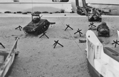
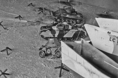
fashioned special effects to make a good show.The first vehicle was launched from the landing craft while it was still well away from the beach. This was a model of one of Hobart's Funnies called an Alligator, basically a remote controlled (yes in full size !) Buffalo troop carrier fitted with a huge exploding mattress on the front to demolish beach defences and walls. This model would swim ashore, climb the beach, and then explode against the promenade (with lots of smoke) to breach the sea wall. The Alligator can just be be seen at the top right of this photo. Next ashore from its own landing craft was a Sherman Flail tank complete with a turret mounted rocket launcher. This model would flail its way up the beach exploding mines as it went, and was quickly followed by an ARK. The ARK (modelled by Steve Kirby) was a converted Centurion tank chassis that carried a set of folding ramps that in full size could be used to create a ramp (or bridge) that other tanks could then cross. In our raid this ARK created a bridge across the section of sea wall demolished by the Alligator. |
 A
1/25th scale Chieftain tank would then make its way ashore from the LCT
firing its main gun at various targets, and eventually crossing the ARK
onto the promenade were its disposable bulldozer blade would be used to
clear away other obstacles . In the photo to the right you
can
actually see the main gun of the Chieftain firing, and it made a very
pleasing "whumph" as the entire tank rocked back on its suspension.
There are more photos and details of the Chieftain tank later
on
this page. A
1/25th scale Chieftain tank would then make its way ashore from the LCT
firing its main gun at various targets, and eventually crossing the ARK
onto the promenade were its disposable bulldozer blade would be used to
clear away other obstacles . In the photo to the right you
can
actually see the main gun of the Chieftain firing, and it made a very
pleasing "whumph" as the entire tank rocked back on its suspension.
There are more photos and details of the Chieftain tank later
on
this page.The photo also shows the scratch built Ferret scout car made by Tom Andrews disembarking from its landing craft. Once the beachhead had been secured a model of an XR311 (a small experimental predecessor of the HumVee) would rush inland to blow up an enemy radar installation amid the requisite pyrotechnics. What made the whole thing quite special was the way that the four modellers involved used their radios to control several models at the same time. As an example I used an 8 Channel homemade RC system to control the following functions. The right hand joystick provide proportional control of the LCT's rudder and twin electric motors, with the third channel operated by switches to control the bow landing ramp and sequential explosions simulating near misses by enemy guns (small charges held on wires extending from the hull underwater to either side of the LCT). The left hand side of the transmitter had two rocker switches that controlled the track motors of the Chieftain tank via channels 4 and 5 of the radio. These gave 1/2 speed reverse, stop, 1/2 speed forward, or full speed forward control to each track motor to let the tank be driven around the beach. Channel 6 of the radio controlled the Chieftain tank's turret traverser, with channel 7 controlling the disposable bulldozer blade and the sequential firing of the 4 rounds of the main gun. Channel 8 operated a change over system in the LCT and XR311. In one position the transmitters channels 1 to 3 controlled the LCT, in the other channels 1 to 3 controlled the XR311 allowing it to drive and fire its TOW missiles. It all sounds quite complicated now, but back then we somehow managed to drive more than one vehicle at a time and the display always seemed to go down well with the spectators (probably because of the copious use of pyrotechnics). All the models carried on the deck of the LCT also had "master On/Off" micro switches operated by pull cords connected to the LCT bow ramp winch, so that any potential radio interference while "at sea" would not result in vehicles causing mayhem on the LCT deck. |
The Chieftain Tank |
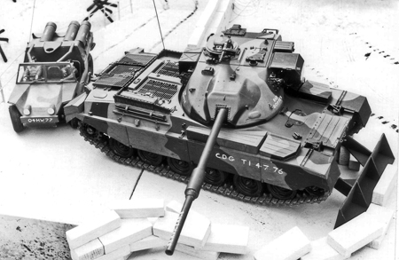 This
photo shows the 1/25th scale Chieftain tank using its bulldozer blade
to clear a wall on the landing beach promenade, with the XR311 scout
vehicle behind it. The model started life as a normal Tamiya
plastic kit, but evolved into something much more exotic. This
photo shows the 1/25th scale Chieftain tank using its bulldozer blade
to clear a wall on the landing beach promenade, with the XR311 scout
vehicle behind it. The model started life as a normal Tamiya
plastic kit, but evolved into something much more exotic.The suspension had to be rebuilt to carry the massive weight of the finished model, and every track link had to be drilled out to fit brass track link pins as the original plastic pins simply snapped under the load. Drive was provided by two Monoperm electric motors driving their tracks via worm and pinions. This was very inefficient but compact, and the home made electronic speed controllers were equipped with a torque compensating system to ensure the correct track speed regardless of load. The end result was that the tank could pull itself up any hill (vertically if it could have got the grip) at the requested speed. The RC system was powered by 4.8V 500mAh Nicads, and the main tank power came from a 6V 1.2Ah Nicad pack. |
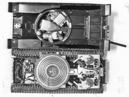 The
photo on the right shows the tank with its top removed, the front of
the tank being towards the left. As previously mentioned all
the
electronics were homemade, although the 27MHz RC receiver was to a
standard published design. The
photo on the right shows the tank with its top removed, the front of
the tank being towards the left. As previously mentioned all
the
electronics were homemade, although the 27MHz RC receiver was to a
standard published design.Against the front glacis plate is the electronic sequential firing board for the main gun, with the speed controller circuit board visible to the left of the turret slip ring plate. Under the slip ring plate are the various batteries for the model, and just visible to the right of the slip ring plate are the three standard RC servos (two rotary and one linear). The rotary servos control the two sets of micro switches used to control the speed of each track, while the linear servo controlled the turret rotation (traverser). The main drive motors and gearboxes are underneath the micro switch assembly. All the power and control for the turret traverser and main gun were connected via the slip ring assembly, and the turret traverse was operated by a Microperm motor and "pile" gearbox. The teeth for the traverser were all filed by hand into the plastic body of the Tamiya kit. |
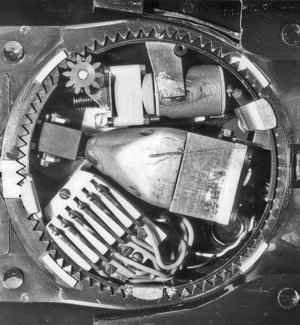 This
final photo shows the internal parts of the turret, with the contacts
for the slip rings at about 7 o'clock. The turret traversing
motor is at the top of the photo, and the hand filed gear ring is
clearly visible. The turret was retained to the body by two
fixed
and one releasable clip so that it could be removed to load the four
rounds into the main gun. As the photo shows the main gun was
massively constructed from brass and aluminium. The
rectangular
block to the right of the turret is the breech block containing four
separate chambers for the rounds, with the tapered block at the centre
linking the four chambers to the barrel. Each "round" of
black
powder was electrically fired, and a sheet of 15 thou plasticard was
sandwiched between the breech block and the tapered link block.
This was the guns secret as it (and the "four into one" holes
in
the tapered block) prevented one round from igniting another, and the
plastic sheet and the barrel allowed just enough pressure to build up
so that the slow burning (uncompressed) black powder produced a very
nice muzzle flash and loud "whumph" sound when firing. This
final photo shows the internal parts of the turret, with the contacts
for the slip rings at about 7 o'clock. The turret traversing
motor is at the top of the photo, and the hand filed gear ring is
clearly visible. The turret was retained to the body by two
fixed
and one releasable clip so that it could be removed to load the four
rounds into the main gun. As the photo shows the main gun was
massively constructed from brass and aluminium. The
rectangular
block to the right of the turret is the breech block containing four
separate chambers for the rounds, with the tapered block at the centre
linking the four chambers to the barrel. Each "round" of
black
powder was electrically fired, and a sheet of 15 thou plasticard was
sandwiched between the breech block and the tapered link block.
This was the guns secret as it (and the "four into one" holes
in
the tapered block) prevented one round from igniting another, and the
plastic sheet and the barrel allowed just enough pressure to build up
so that the slow burning (uncompressed) black powder produced a very
nice muzzle flash and loud "whumph" sound when firing.Although I no longer have the means to operate the model (the RC gear having long since ceased to work) I still keep this model tank as a reminder of what we once achieved. |
The XR311 |
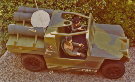 This
little model was built using plasticard from a single photograph that I
spotted in a book of Armoured Fighting Vehicles, and its diminutive
size (for a radio controlled model car in 1976) can be judged by the
50p coin balanced on it. This
little model was built using plasticard from a single photograph that I
spotted in a book of Armoured Fighting Vehicles, and its diminutive
size (for a radio controlled model car in 1976) can be judged by the
50p coin balanced on it.The wheels and tyres came from a plastic model car kit, but every other part was scratch built and each rear wheel was powered by a Milliperm electric motor via a purpose built brass gearbox. The end result was a very nippy little model with full proportional steering and forward/ reverse speed control and enough power to climb any slope. The bracket over the cab was intended to mount the TOW missile launcher, which unfortunately I never managed to make work well enough to be worthwhile using in the commando raid display. |
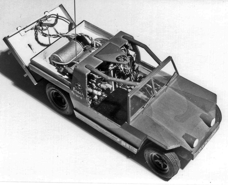 This photo shows the internals
of the XR311, the drivers/ seats and rear body load deck having been
removed. This photo shows the internals
of the XR311, the drivers/ seats and rear body load deck having been
removed.The two motors and gearboxes fill the space between the rear wheels, and the steering servo fills the space directly below the driver's position. The rear of the cab houses the homemade 27MHz radio control receiver and the proportional speed controller. The model used five 1.2V 500mAh Nicad cells to power everything, with three cells hidden in the TOW missile containers on the rear load deck and two more hidden inside the bonnet of the vehicle. The passenger foot well contained the speed controllers forward / reverse relay as well as the LCT / XR311 changeover relay system (described in the main paragraphs above) and the TOW missile igniter circuitry. Sandwiched in between the drive motors was the master "pull cord" micro switch that was mentioned in the section about the LCT. This little model was tough, and was frequently jumped from the sea wall (see previous photos) back onto the beach as it returned to the LCT after the raid, and on one occasion it had to be rescued from the murky depths of a lake after I missed the LCT ramp when attempting to load at full speed. Trampling about in filthy water, feeling for the model with my toes, certainly provided a different experience to that day's display ! |
A Land Rover for charity fund raising |
 This
was the last radio controlled model that I ever built "from scratch"
and it was made in 1985 when I was already spending all my hobby time
competing in full size Off Road events (click
here to see more about that hobby).
For the Land Rover club's annual rally it seemed like a good
idea
to raise funds for local charities by letting the rally visitors have a
go at driving a model vehicle around a simulated off road course, so a
suitable obstacle course was created on two large sheets of hardboard
while I built the Land Rover. This
was the last radio controlled model that I ever built "from scratch"
and it was made in 1985 when I was already spending all my hobby time
competing in full size Off Road events (click
here to see more about that hobby).
For the Land Rover club's annual rally it seemed like a good
idea
to raise funds for local charities by letting the rally visitors have a
go at driving a model vehicle around a simulated off road course, so a
suitable obstacle course was created on two large sheets of hardboard
while I built the Land Rover.The body came from a very old Monogram plastic kit that I just happened to have in the back of a cupboard, but every other part of the model was specially built including the 27MHz radio control receiver and the electronic speed control. Power was supplied from a single 6V 500mAh Nicad pack for both the radio and drive motor, with the Milliperm electric motor driving both rear wheels via a homemade brass gear box The original Monogram kit tyres were moulded from hard plastic, so a set of soft rubber tyres were found in another old plastic kit, and brass wheels were turned on my lathe to carry the tyres and the Monogram plastic wheel trim discs.. |
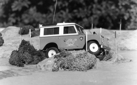
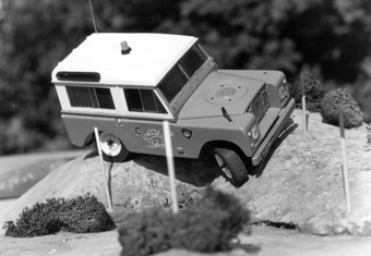 The
big problem that had to be overcome was the suspension, and right from
the start I didn't think that springs of any type would work very well
on such a small model (it was only 150mm long). To be able to
drive across the obstacles as shown in the two photos the models wheels
had to travel a long way up and down, so I designed a system that
mechanically linked the front and rear beam axles together such that if
a front wheel needed to "go up" the diagonally opposite rear wheel
would also be forced "up". The
big problem that had to be overcome was the suspension, and right from
the start I didn't think that springs of any type would work very well
on such a small model (it was only 150mm long). To be able to
drive across the obstacles as shown in the two photos the models wheels
had to travel a long way up and down, so I designed a system that
mechanically linked the front and rear beam axles together such that if
a front wheel needed to "go up" the diagonally opposite rear wheel
would also be forced "up".As the photos show the little model was as capable of crossing very rough terrain as it's full size counterpart. |
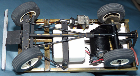 This
photo shows the underside of the model and you can see how the front
and rear axle assemblies are mounted to the longitudinal pivot shaft.
The front axle has the steering servo mounted to its frame,
while
the rear axle frame also carries the motor and gearbox. This
photo shows the underside of the model and you can see how the front
and rear axle assemblies are mounted to the longitudinal pivot shaft.
The front axle has the steering servo mounted to its frame,
while
the rear axle frame also carries the motor and gearbox.All of the chassis was made using the K&S range of brass sections, and you may just be able to see how a square box section has been fitted over the steering servo output boss to transfer the steering motion to the front wheels. |
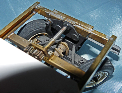 This
final photo shows the top view of the front axle assembly. A
lever connects from the left hand side of the "rocking" front axle to
the crank lever mounted inside the front of the chassis. The
shaft from the front crank is then connected to its counterpart of the
rear axle by the two small gears visible in the photo. The
end
result is that the body and chassis are always kept "level" as the
front and rear axles swing up and down in opposite directions, and a
big benefit over suspension springs is that the full weight of the
model is always kept equally spread over the four wheels (the model
never ends up with the lowest wheel having very little weight on it as
happens with normal spring suspension). This gave the model
its
ability to keep driving over extremely rugged terrain despite only
having rear wheel drive. This
final photo shows the top view of the front axle assembly. A
lever connects from the left hand side of the "rocking" front axle to
the crank lever mounted inside the front of the chassis. The
shaft from the front crank is then connected to its counterpart of the
rear axle by the two small gears visible in the photo. The
end
result is that the body and chassis are always kept "level" as the
front and rear axles swing up and down in opposite directions, and a
big benefit over suspension springs is that the full weight of the
model is always kept equally spread over the four wheels (the model
never ends up with the lowest wheel having very little weight on it as
happens with normal spring suspension). This gave the model
its
ability to keep driving over extremely rugged terrain despite only
having rear wheel drive. |