Of
all the modifications I have made to my Feldbahn, and the Stafford
before it, this is by far the most controversial. To some
having
a steam engine without injectors is almost sacrilegious while others
see it as a way of embracing modern technology, and surprisingly people
I have expected to take one stance have often taken the opposite.
My personal preference is to have injectors feeding the water
into the boiler simply because that's how it's done on a "real" steam
engine. So why have I made the change ?
After a couple
of years of tinkering I had the injectors on my Stafford working
perfectly and you can read all about those changes on the Stafford
pages of this website. All you had to do on the Stafford was
turn
on the water, turn on the steam, and water was fed into the boiler.
It was so reliable that you only needed to look down to see
when
the boiler had enough water in it. The Stafford had
eventually
covered over 500 miles and I hadn't even had to clean either injector.
So far as I was concerned the injector system was totally
reliable.
However
when I exchanged the Stafford for my Feldbahn, despite having modified
the injector system to incorporate all I had learnt from the Stafford,
I only did one lap of the Pinewood track before returning to the yard.
I simply could not operate the injectors while driving.
Eventually I learnt that the Feldbahn injectors needed
special
treatment. You had to turn on the water, turn on the steam,
then
throttle back the water until the injector picked up, then reopen the
water flow and set it "just so" depending on variables like boiler
pressure and temperature to keep the injector operating nicely.
This meant that the driver spent a lot of time looking down
at
the injector overflow and not where he was driving. Once I
had learnt the technique it wasn't really a problem on the
smooth
running
Pinewood track, but on rough tracks the injectors had a tendency to
stop on most of the track bumps. The driver thus had to go
through a full injector restart procedure, and just as you had got it
going you would hit the next bump and start all over again.
To
try to solve this annoyance I tried purchasing a couple of different
injectors but these either exhibited the same, or in one case, other
problems. I even resorted to asking Station Road Steam about
where they had purchased the Stafford's injectors but they were unable
to help.
Having left Pinewood driving
the Feldbahn just wasn't fun so I started investigating what could have
been wrong. Most of the basics for reliable injectors had
already
been covered. The output pipe to the clack was quite short,
the
bends were smooth with large radii, and the pipes were the same size as
on the Stafford with no obstructions in them. Assuming that
commercial injectors wouldn't be sold if they didn't work the obvious
thing to look at was the water feed to the injector. The
advice
here is generally that of making sure the injector can receive enough
water, so you don't want anything like tight bends or small pipes to
restrict the water flow. The head of water feeding the
injector
will also have an affect so the greater height of the Stafford's saddle
tank may help, but probably not by much. The
Stafford and
Feldbahn both use 8mm pipe to feed the injectors, and I had gone as far
as using 15mm pipe in the tender, dropping down to two 9mm pipes
linking the tender to my Feldbahn, and finally 8mm through the
footplate mounted valves. The injectors fitted to the
Stafford
and Feldbahn are rated at 2 2/3rd pints per minute, and with the
footplate valve output pipe removed measurements showed that much water
would flow out of the valve in 47 seconds. However if the
same
measurement was made at the end of the pipe normally connected to the
injector it took 135 seconds for the 2 2/3rd pints to flow.
This
is half the rate that the injector is supposed to move so the injector
actually has to suck the feed water from the tank. The reason
for
this restriction is the injector design. All the of the
injectors
we normally fit to the Stafford's or Feldbahn's use a 3/8"x32 union nut
and
nipple for 1/4" diameter pipe, and it's the restriction of that nipple
that drastically reduces the flow rate. The Stafford had the
same
restriction and worked satisfactorily, but I can't help wondering if
this design restriction is actually part of the problem.
Since I
don't have the capabilities of making my own injectors I will never
know.
Anyway, for several years I have been watching the
price of suitable electric pumps fall and while pondering what I was
going to do about the Feldbahn's injectors I spotted that I could now
buy two pumps and a battery to operate them all day for less than the
price of a single injector. Having purchased a pump I tested
it
while conducting a steam test on the Feldbahn and was very
impressed by its capabilities and quiet operation. On test
with
the boiler at 120 psi the pump happily fed 3 pints per minute into the
boiler, which is slightly more than the injector is supposed to do.
That basically settled any doubts in my mind; my Feldbahn was
going to have an electric pump fitted to improve the reliability of the
boiler water feed.
Having
decided that I was going to
fit an electric pump the problem was where to fit it. My new
tender
for the Feldbahn had not been designed to have space for the pump, and
wherever it ended up on the tender I was going to have to install a
high
pressure feed pipe between the tender and engine. It was all
looking a
bit difficult until I suddenly realised that the pump would fit very
nicely inside the original water tank space on the Feldbahn.
Putting
the pump there also meant that the high pressure piping was all on the
Feldbahn and the existing tender to engine plumbing that had been
feeding the injector could now feed the pump. From then on it
was no
longer a case of fitting one pump to back up the remaining injector.
My Feldbahn would now have two electric pumps and no
injectors !
|
 Electric
pumps of this type are sold with a variety of maximum pressure and
supply voltage ratings with the cheapest only costing about £12 (as of
August 2016) so you can select a pump to suit most model steam engines.
The pump I chose for use on the Feldbahn is generally
advertised
as being suitable for use in misting systems (air / moisture
conditioning) or for window cleaning (those long pole cleaners you see
being used to clean office block windows). The Pro Pump 160
operates from 12 Volt d.c. and is advertised as being capable of
providing 160 psi and of pumping 8 litres per minute. It's
rated
at 100 Watts (e.g. 8.3 Amps on 12V) and it also incorporates a limit
switch to stop the pump if the output pressure exceeds 160 psi. Electric
pumps of this type are sold with a variety of maximum pressure and
supply voltage ratings with the cheapest only costing about £12 (as of
August 2016) so you can select a pump to suit most model steam engines.
The pump I chose for use on the Feldbahn is generally
advertised
as being suitable for use in misting systems (air / moisture
conditioning) or for window cleaning (those long pole cleaners you see
being used to clean office block windows). The Pro Pump 160
operates from 12 Volt d.c. and is advertised as being capable of
providing 160 psi and of pumping 8 litres per minute. It's
rated
at 100 Watts (e.g. 8.3 Amps on 12V) and it also incorporates a limit
switch to stop the pump if the output pressure exceeds 160 psi.
In
practice the 8 Litres per minute only occurs when the pump is not
providing water against any pressure, and my measurements show that it
pumps 1.7 Litres per minute (3 Pints per minute) against the 120 psi
boiler pressure while drawing just over 5 Amps from the 12 Volt battery.
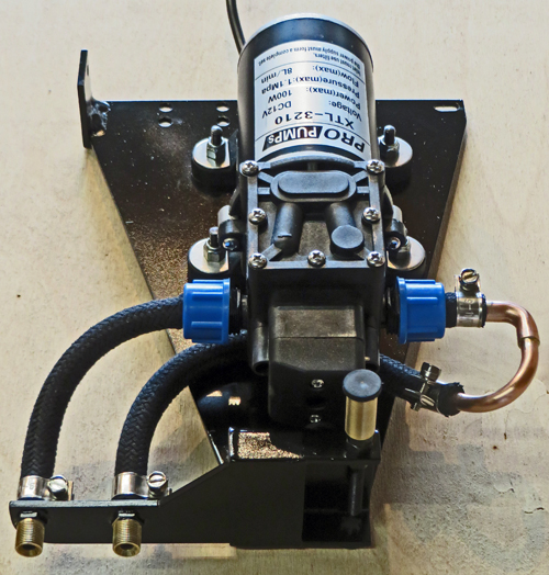
The
revised body style of my Feldbahn no longer has the two bolts that
previously retained the water tank, and without removing the cab I
could not drill any suitably inconspicuous holes to attach the pump
so I had to mount the pump using fixings that were
available. The large triangular plate to which the pump is
attached mounts at the top to one of the pressure / vacuum gauge
bracket bolts (depending on which side of my engine you are looking
at) and to the relevant spectacle plate bracing strut bolt.
At
the bottom are two rubber feet with the one fitted to the brass bush
being mounted on a length of studding. When the assembly has
been
positioned inside the water tank space and the top fixings are tight
the studding is adjusted to tightly brace the rubber feet across the
bottom of the water tank space.
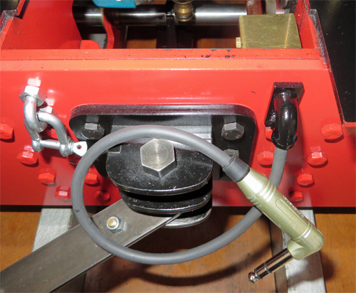
The
flexible black tubing is sold for car fuel injection systems and rated
at 145 psi so it is adequate for the boiler pressure but I would be
relying on its designed factor of safety if a blockage caused the pump
pressure to rise to the 160 psi cut off. In order to not
exceed
the tubing's minimum recommended bend radius the pump's position within
the water tank space has been biased towards the front of the engine
which meant that copper pipe had to be used on one side of the pump to
create the tight bend radii. The copper pipe and threaded
output
connections at the bottom left all have lipped ends to help retain the
flexible tubing. The hose clips are standard automotive fuel
hose
clips.
|
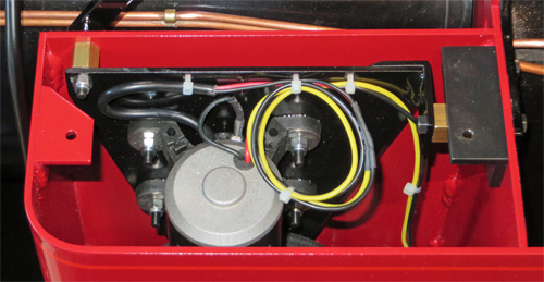 This
photo shows one of the pump assemblies installed inside the Feldbahn's
left hand water tank space. The yellow and black wires
supplying
the power for the pump are 18 AWG silicone wire rated at 16 Amps but
more importantly also rated for operation at 200 degrees Centigrade.
This is crucial as the wires have to run close to the firebox
where normal PVC wire insulation would melt. This
photo shows one of the pump assemblies installed inside the Feldbahn's
left hand water tank space. The yellow and black wires
supplying
the power for the pump are 18 AWG silicone wire rated at 16 Amps but
more importantly also rated for operation at 200 degrees Centigrade.
This is crucial as the wires have to run close to the firebox
where normal PVC wire insulation would melt.
The circular loop in
the wiring is a Service Loop which allows the wires to be longer than
needed so that spare wire is available in case the pumps have to be
removed
requiring the wires to be cut and then reconnected.
|
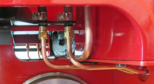 The
water connections to and from the pump use 1/4" diameter copper tube
with normal 3/8"x32 unions and pipe nipples. The pipes have
been
routed through the convenient hole in the footplate support.
The
larger 10mm diameter pipe in the photo provides a conduit for the pump
wiring and these L shaped pipes on each side of the engine are attached
to the footplate by means of silver soldered brackets and the
existing cab mounting bolts. Each wire conduit is a slide fit
into a copper tube T piece attached to the top of a conduit that runs
down and under the engine. Unfortunately that T piece is
impossible to photograph. The
water connections to and from the pump use 1/4" diameter copper tube
with normal 3/8"x32 unions and pipe nipples. The pipes have
been
routed through the convenient hole in the footplate support.
The
larger 10mm diameter pipe in the photo provides a conduit for the pump
wiring and these L shaped pipes on each side of the engine are attached
to the footplate by means of silver soldered brackets and the
existing cab mounting bolts. Each wire conduit is a slide fit
into a copper tube T piece attached to the top of a conduit that runs
down and under the engine. Unfortunately that T piece is
impossible to photograph.
|
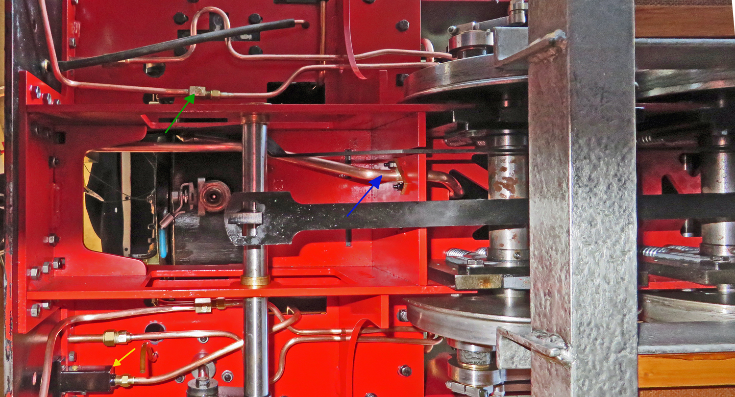 In
this unusual view from underneath my Feldbahn you can see how the pump
wiring conduit (blue arrow) has been routed through one of the holes in
the cross brace that appear to have been intended for an axle pump.
Nearer the rear axle the conduit runs vertically up to the T
piece mentioned above, and at the left of the photo the conduit ends at
the rear buffer bean underneath the removable section of the footplate.
The conduit thus protects the wires all the way from the
electrical junction box on the inside of the rear buffer beam to where
the wires enter the old water tank spaces. In
this unusual view from underneath my Feldbahn you can see how the pump
wiring conduit (blue arrow) has been routed through one of the holes in
the cross brace that appear to have been intended for an axle pump.
Nearer the rear axle the conduit runs vertically up to the T
piece mentioned above, and at the left of the photo the conduit ends at
the rear buffer bean underneath the removable section of the footplate.
The conduit thus protects the wires all the way from the
electrical junction box on the inside of the rear buffer beam to where
the wires enter the old water tank spaces.
The photo also
shows how the pipe between the pump and the boiler clack valve has a T
piece fitted (green arrow) with the teed section leading to a drain
cock on the inside of the rear buffer beam. This provides me
with
a simple way of draining the pipe when the Feldbahn is being stored.
The
pipe with the horseshoe shaped bend in it near the top left of the
photo is the pipe connecting the water inlet on the rear buffer beam to
the pump. Previously the buffer beam water inlets had been
connected to the footplate water valves but both of those valves had
now been removed and the holes in the footplate blanked off.
The
bend was created to allow some flexibility in the
pipes actual length because its shape has no natural way of allowing
for slight changes in its length due to it being a
dead straight "a to b" pipe. The pipe feeding the other pump
is
similarly bent although the bend is hidden behind the brake bar in the
photo.
Those of you familiar with Feldbahn's may be
wondering what the black box marked with the yellow arrow is.
That is the electrical junction box for the engines headlamp
wiring.
If you would like to see this photo as a larger image then please click
on it to open a larger version in a new window .
|
 The
electrical connection between the Feldbahn and its tender uses a 3 core
silicone sleeved cable and a stereo jack plug. If you decide
to
use a similar method make sure that you purchase a jack plug that has a
suitable current rating. The ones I use were rated at 10 Amps. The
electrical connection between the Feldbahn and its tender uses a 3 core
silicone sleeved cable and a stereo jack plug. If you decide
to
use a similar method make sure that you purchase a jack plug that has a
suitable current rating. The ones I use were rated at 10 Amps.
Silicone
sheathed wire was again chosen for its ability to resist heat. If
you drop a hot ember from the fire on it you don't want the insulation
to instantly melt.
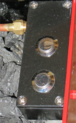
The
brass coloured square on the inside of the buffer beam is the
electrical junction box where the 3 core cable connects to the
individual wires leading to the two pumps. It also
has a
cable tie inside it acting as a retaining clamp to prevent the 3 core
cable from being pulled out of the buffer beam.
|
 The
pumps are controlled by a pair of push button switches mounted in a
small die cast box located in the front left-hand corner of the tender
coal space. To prevent the switches getting jammed up by coal
dust etc. I used switches with an IP65 rating which means that they are
water and dirt proof. The
pumps are controlled by a pair of push button switches mounted in a
small die cast box located in the front left-hand corner of the tender
coal space. To prevent the switches getting jammed up by coal
dust etc. I used switches with an IP65 rating which means that they are
water and dirt proof.
Non latching push button switches were
chosen in place of latching switches (either push button or toggle
type) because they would ensure that the operator had to keep pushing
the button to pump water into the boiler. If a more
conventional
latching switch had been used the operator could leave the engine with
the pump running and thus overfill the boiler to the point where there
was no steam space left at all and water was blasting out of the safety
valve. That would potentially be a very nasty situation and
had
to be avoided.
|
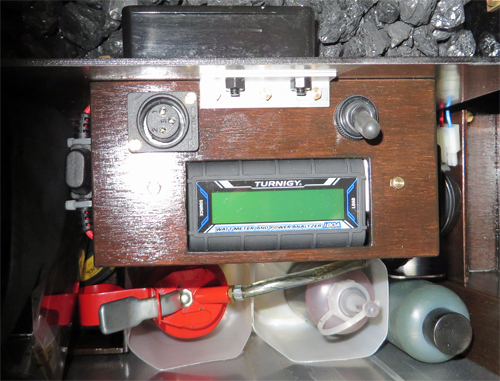 This
photo shows the storage space inside my Feldbahn's tender where the 20
Ah battery for the electric water pumps is situated underneath the
wooden switch panel. There is still sufficient space for the
various oils and water treatment to be carried as well as some tools
and waterproof clothing. This
photo shows the storage space inside my Feldbahn's tender where the 20
Ah battery for the electric water pumps is situated underneath the
wooden switch panel. There is still sufficient space for the
various oils and water treatment to be carried as well as some tools
and waterproof clothing.
The wooden panel helps to hold the
battery in position and has the battery charging socket and power On /
Off switch mounted on it together with a 15 amp fuse in a holder on the left-hand side. The item with the green coloured
screen
on it is a power monitor for the pump's 12 Volt battery. If
you
have seen electric locomotives operating on a miniature railway you may
have noticed that they frequently incorporate coloured LED's to show
the drive batteries state of charge. For a 12 Volt battery
they
tend to have three LED's denoting full, OK or discharged. For
only a couple of pounds more you could have one of these power
monitors. The display shows not only the battery voltage but
also
the current being drawn from the battery; and on a cyclic section of
the display they show the total ampere hours drawn from switch on, peak
current drawn, and the elapsed running time. This is far more
useful than three LED's and as the unit can measure up to 180 Amps and
operate from a 24 Volt supply it can also be used to monitor the drive
batteries of most miniature railway locomotives.
|
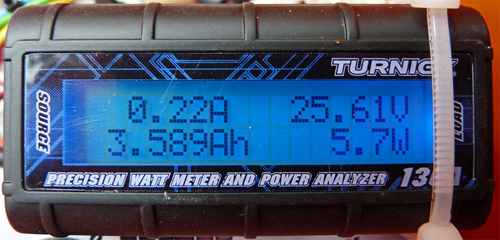 Here
is a photo of the wattmeter's display when I was using it to monitor
the batteries of one of my electric locomotives. At the top
right
is the battery voltage (the locomotive used a pair of 12 Volt
batteries), with the current being drawn at the top left (the loco was
stationary when photographed and thus not drawing any significant
current. At the bottom left the cyclic display is showing the
total number of ampere hours drawn from the battery since switch on.
The bottom right shows the number of Watts supplied by the
battery. Here
is a photo of the wattmeter's display when I was using it to monitor
the batteries of one of my electric locomotives. At the top
right
is the battery voltage (the locomotive used a pair of 12 Volt
batteries), with the current being drawn at the top left (the loco was
stationary when photographed and thus not drawing any significant
current. At the bottom left the cyclic display is showing the
total number of ampere hours drawn from the battery since switch on.
The bottom right shows the number of Watts supplied by the
battery.
For little more than the LED monitor you get an
awful lot more information about the state of you battery and what has
been going on. By using this monitor I leant that the two
electric pumps on my Feldbahn used just over 2 ampere hours for a 5 1/2
hour steaming session covering 8.95 miles. The 20 Ah battery
I am
using thus has far more capacity than needed for a day at the track.
|
I
think that this page should provide all the information you need about
using electric pumps to replace the injectors on your model steam
engines. I am certainly extremely happy with their
performance
even though I would prefer to use injectors, but fitting the pumps has
made driving my Feldbahn enjoyable again as well as letting me
concentrate on where the engine is going rather than looking down at
the injector system.
Finally for those of you who would say
that an electric boiler feed pump has no place on a model locomotive I
would suggest that you consider the following fact. Full size
railway engines generally do not have axle pumps fitted, but how many of you are
happy to use them on your models ? |