 |
 |
|
Buidling a tender for a Feldbahn
 While
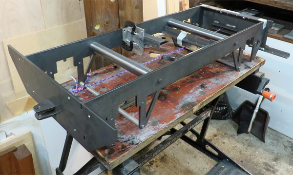
the fabricators were building the tender body I had been progressing
with the chassis and this photo shows it jigged up ready for MIG
welding. The two solid round steel bars are simply jig beams to
correctly space and align the chassis sides. These would be removed after the
welding was complete. As these were too large to face, drill, and
tap on my lathe I asked a local machine shop to make them and they very
kindly only charged for those operations and not for the material,
provided that I returned the parts to them after use. A few more
pennies were thus saved ! While
the fabricators were building the tender body I had been progressing
with the chassis and this photo shows it jigged up ready for MIG
welding. The two solid round steel bars are simply jig beams to
correctly space and align the chassis sides. These would be removed after the
welding was complete. As these were too large to face, drill, and
tap on my lathe I asked a local machine shop to make them and they very
kindly only charged for those operations and not for the material,
provided that I returned the parts to them after use. A few more
pennies were thus saved !Various brackets were also welded in to support parts of the vacuum braking system, footrests, and to mount the tender body. I don't think that I have ever placed so much faith in my CAD design being accurate before. With most of those brackets having been drilled before welding the design had to be right first time, and thankfully everything worked out OK. |
||||||
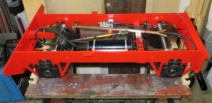 This
photo shows the chassis during installation of the vacuum braking
system. The vacuum servo is just in front of the rear axle (left
hand side of the photo) and the red painted longitudinal bracket to the
rear of the servo will eventually be used to secure the various pipes
and cables using tie wraps. The vacuum brake reservoir is on the
right hand side of the chassis between the axles, while the copper tube
will become the pipe that takes water from the tender tank to feed it
to individual connections for the two locomotive injectors. This
photo shows the chassis during installation of the vacuum braking
system. The vacuum servo is just in front of the rear axle (left
hand side of the photo) and the red painted longitudinal bracket to the
rear of the servo will eventually be used to secure the various pipes
and cables using tie wraps. The vacuum brake reservoir is on the
right hand side of the chassis between the axles, while the copper tube
will become the pipe that takes water from the tender tank to feed it
to individual connections for the two locomotive injectors.The PNP Railways wheels and axles are mounted using "take up bearings" which provide a very convenient solution to axle boxes and suspension. All you have to do is get the right springs fitted to carry the load, and that is something I never seem to get right first time despite hours of calculation using spreadsheets. The only disadvantage to take up bearings is that they only seem to come painted green, so I had to get them grit blasted before treating them with Metal Black to obtain black coloured axle boxes. | ||||||
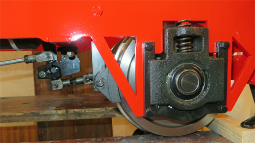 This
photo shows a close up of one of the take up bearings. You can
see how a 3mm thick U shaped keeper retained by four 2 ba bolts is used
to thicken the 6mm thick chassis so that the take up bearing slides
smoothly. The suspension spring simply drops into the top of the
bearing and locates around a lug formed when the chassis side was laser
cut. This
photo shows a close up of one of the take up bearings. You can
see how a 3mm thick U shaped keeper retained by four 2 ba bolts is used
to thicken the 6mm thick chassis so that the take up bearing slides
smoothly. The suspension spring simply drops into the top of the
bearing and locates around a lug formed when the chassis side was laser
cut.The brake linkage compensator can also be seen in this photo. The brake bar cross beams link back to the servo operating lever which pivots in slotted brackets attached to the chassis. This allows the operating lever to adjust its position and thus apply equal pressure to the brakes on both axles. If the lever simply pivoted around a fixed pivot it would be very difficult to set the brake linkages up to ensure even brake block pressure on both axles. | ||||||
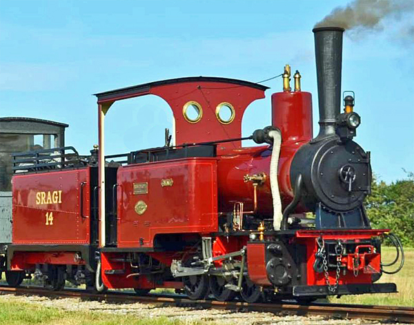
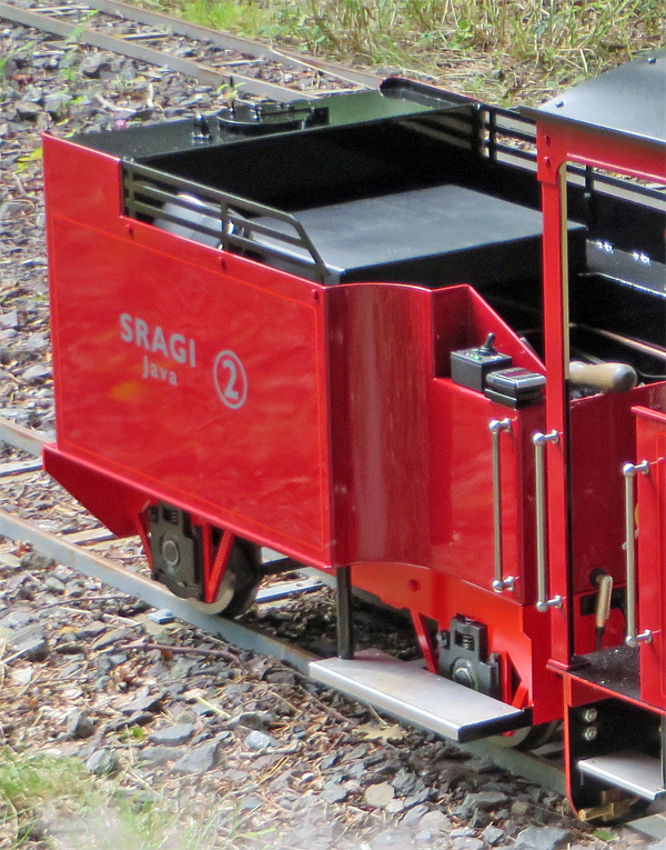 This
photo shows the completed tender coupled to my Feldbahn. You can
see how the foot rests are positioned in relation to the front axle to
ensure stability and how the inset section of the tender body allows
the drivers feet and legs to fit low and as close to the wheels as
possible. By adding handrails and chequer plate to match the
dummy steps fitted to the Feldbahn the foot rests don't look too out of
place. This
photo shows the completed tender coupled to my Feldbahn. You can
see how the foot rests are positioned in relation to the front axle to
ensure stability and how the inset section of the tender body allows
the drivers feet and legs to fit low and as close to the wheels as
possible. By adding handrails and chequer plate to match the
dummy steps fitted to the Feldbahn the foot rests don't look too out of
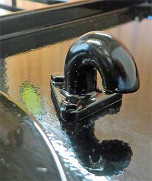
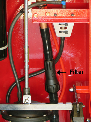
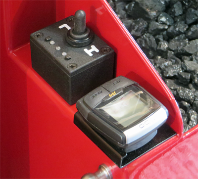
place. The padded driver's seat acts as a cover to the central storage section of the tender and the water tank has been deliberately raised behind the seat to deter drivers from sitting too far back and upsetting the stability of the tender. Laser cut side rails finish the tender sides in a similar fashion to that of the full size tender. Note how the sides of the tender and the bulkhead behind the driver's seat are raised above the top of the water tank so that any over spill when filling will drain off the back of the tender and not spill onto the driver's seat. The water tank has a hinged lid (which prevents it from getting lost) but as I discovered it makes a surprisingly good seal against the tank rim. Thankfully I found this out when testing the tender for water tightness before use because the water flow from the injector feed pipes was quite low. Adding a goose neck breather to the top of the tank overcame that problem. Having used the tender with the Feldbahn I am pleased to say that it has met all my objectives, is very comfortable, and rides rough track very well. The firing irons fit comfortably on top of the coal and although the driver sits quite close to the Feldbahn there is no problem when firing while driving. With so much coal and water onboard you can happily stay out on track and away from water or coaling facilities for several hours at a time if just pottering about. Since completing the tender two changes have been made to it. The first, the goose neck breather, has already been mentioned. This was fabricated by silver soldering a pair of 8mm copper elbows together because normal tube benders simply can't bend pipe tight enough. There is a photo of the finished goose neck below. The second change was the addition of a water filter into the injector feed pipe. Neither my Stafford or Feldbahn have ever had water filters fitted in their injector feeds, but between them they have covered over 700 miles with only one incident when a piece of debris stopped an injector from working. However a water filter has always seemed like a good idea that I have never got around to until now. A chance observation when searching on-line for spares for my lawn mower resulted in me spotting an in-line water filter suitable for 16mm (5/8") pipe, which by a happy coincidence is the diameter of the water feed pipe under the tender. Having bought one of the filters I found that it can easily be dismantled for cleaning and that the mesh filter inside it looks perfect for filtering injector feed water. The photo below shows it installed underneath the tender. The other photo below shows the speedometer mounted at the front of the tender. Behind it is a small box with a switch to control the brightness of the Feldbahn's headlamp; H (bright), L (dim) with a centre Off position. If either headlamp brightness is selected the train tail lamp is also switched On. The box also has three LED's fitted (Green, Yellow, and Red when lit) which show the driver how much water is left in the tender. Two magnetic float switches (more normally used in fish tanks) are fitted in the water tank which operate relays to illuminate one LED at a time. The position of the float switches was set so that the Green LED is lit for anything over 1/2 a tank of water, the Yellow LED for 1/4 to 1/2 a tank, and the Red LED for less than 1/4 of a tank. Power for the level indicators and lights comes from a 12V NiCad pack stored in the tender's tool space. | ||||||
|
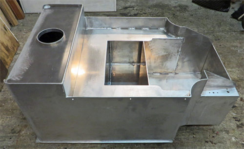 My
completed design had two major components, the chassis and the tender
body. The chassis was to be laser cut from 6mm mild steel plate
and would be within my welding capabilities once jigged up. The
body was simply too difficult for me to construct myself as it required
several different bend radii and had to have a watertight non rusting
tank incorporated into it. After talking it through with a couple
of local sheet metal fabricators I decided that it would be built from
3mm thick aluminium sheet and seam welded. Once I had completed
all the CAD drawings I accepted the quoted price and construction was
underway.
My
completed design had two major components, the chassis and the tender
body. The chassis was to be laser cut from 6mm mild steel plate
and would be within my welding capabilities once jigged up. The
body was simply too difficult for me to construct myself as it required
several different bend radii and had to have a watertight non rusting
tank incorporated into it. After talking it through with a couple
of local sheet metal fabricators I decided that it would be built from
3mm thick aluminium sheet and seam welded. Once I had completed
all the CAD drawings I accepted the quoted price and construction was
underway.