 |
 |
|
Headlamp
 The
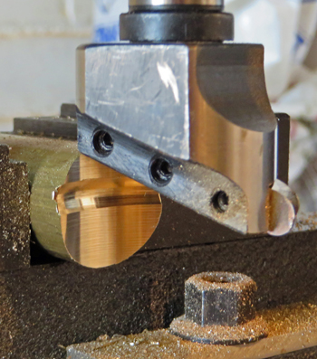
biggest problem with building the headlamp was always going to be
shaping the circular top section and lower box section to fit snugly
around the circular body and its raised ridge. Thankfully my
workshop now includes a small milling machine so both parts could be
shaped using a flycutter with the tool ground to match the shape of the
body's ridge. The only tricky part of this operation was to
get
the cutter correctly set to machine the radii, but careful measurement
resulted in the parts fitting first time. The photo shows the
brass bar and flycutter after machining. The
biggest problem with building the headlamp was always going to be
shaping the circular top section and lower box section to fit snugly
around the circular body and its raised ridge. Thankfully my
workshop now includes a small milling machine so both parts could be
shaped using a flycutter with the tool ground to match the shape of the
body's ridge. The only tricky part of this operation was to
get
the cutter correctly set to machine the radii, but careful measurement
resulted in the parts fitting first time. The photo shows the
brass bar and flycutter after machining.The next stage was to put the bar into the lathe to machine it to the correct shape and to turn the spherical top section. You can buy (or make) spherical turning attachments for lathes but I always resort to using a spreadsheet to define the X and Y cut distances. Depending on the required shape I simply decide to take 0.1mm cuts in one direction to a depth of "x" in the other. For a spherical shape simple trigonometry will tell you the depth to cut for each 0.1mm increment and for more awkward shapes such as ellipses the values can be calculated using the CAD drawing programs. Once you have a (sometimes very) long list of X and Y values then it's simply a case of making all the cuts and finally smoothing off the "steps" using fine files and emery paper. From starting to create the EXCEL spreadsheet of values to finishing the spherical turning and polishing took less than 45 minutes which may well have been quicker than trying to setup a spherical turning tool. With the exception of the lamp glass retaining bezel and a lid for the lower box section all of the various parts of the headlamp were initially screwed together and once everything fitted correctly all the joints were silver soldered. Although it can't be seen in the photographs there is an inner retaining ring machined from Delrin that keeps the front of the lamp centered in the body and at the same time acts as a spacer between the front of the lamp and the "glass" (although the glass is actually polycarbonate). The bezel that retains the "glass" was again turned from brass bar and is attached to the lamp body using three 9BA roundhead screws. The lower box section forms the electrical junction box and its lid is held in place by a 6BA bolt. |
|||
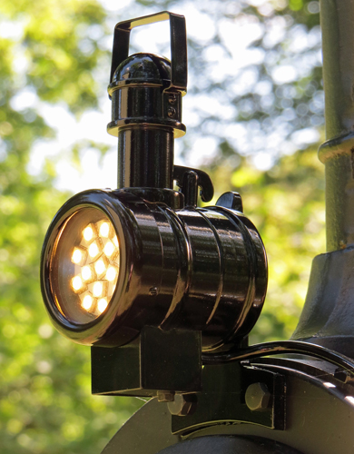
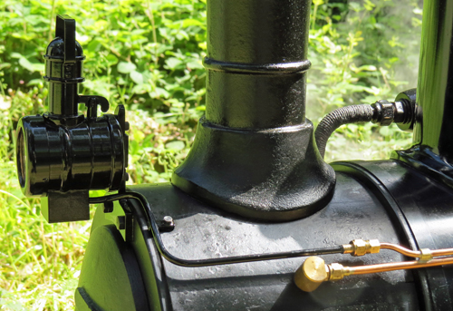 This
photo shows the completed headlamp fitted to my Feldbahn together with
the first part of my solution to wiring it to the batteries.
Because
the MR11 lamp completely fills the internal space of the headlamp there
was never going to be any space to fit batteries inside the lamp, and
in any case a lamp of this size could never contain sufficient battery
power to operate a truly "bright" lamp for any sensible period of time.
So right from the start I knew that I would have to operate
the
headlamp from batteries in the driving truck and that meant creating a
rugged wiring system that could withstand the high temperatures found
on a steam locomotive. Silicone insulated wiring was chosen
because it can operate at 200 degrees Centigrade but it still required
mechanical protection so it was run through copper tubing.
This
had the added benefit that only one wire was actually required with the
copper tubing forming the return current path (earth). In the
photo you can see that a length of tube painted black runs from the
lamp to a pipe fitting adjacent to the blower pipe smokebox connection.
For added security this tube is also bolted to the smokebox. This
photo shows the completed headlamp fitted to my Feldbahn together with
the first part of my solution to wiring it to the batteries.
Because
the MR11 lamp completely fills the internal space of the headlamp there
was never going to be any space to fit batteries inside the lamp, and
in any case a lamp of this size could never contain sufficient battery
power to operate a truly "bright" lamp for any sensible period of time.
So right from the start I knew that I would have to operate
the
headlamp from batteries in the driving truck and that meant creating a
rugged wiring system that could withstand the high temperatures found
on a steam locomotive. Silicone insulated wiring was chosen
because it can operate at 200 degrees Centigrade but it still required
mechanical protection so it was run through copper tubing.
This
had the added benefit that only one wire was actually required with the
copper tubing forming the return current path (earth). In the
photo you can see that a length of tube painted black runs from the
lamp to a pipe fitting adjacent to the blower pipe smokebox connection.
For added security this tube is also bolted to the smokebox.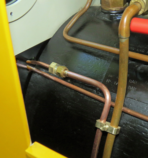 The
second section of tube runs parallel to the blower pipe and is silver
soldered to the blower pipe using brass spacers every 150mm.
Inside the cab another tube union connects the wiring tube to
a third section of tubing that runs to an electrical junction box
fitted to the rear buffer beam. By making the wiring "tube"
in
three sections it not only became a simpler tube to make and fit but
also makes it much easier to thread the silicone wire through the
tubes.
Even so it was still impossible to simply push the wire
through
the third section of tube because friction through the bends becomes
greater than
the force you can apply to the wire without it just folding up on
itself. Luckily I have a simple trick to resolve that problem
and
you can read about it by clicking
here. The
second section of tube runs parallel to the blower pipe and is silver
soldered to the blower pipe using brass spacers every 150mm.
Inside the cab another tube union connects the wiring tube to
a third section of tubing that runs to an electrical junction box
fitted to the rear buffer beam. By making the wiring "tube"
in
three sections it not only became a simpler tube to make and fit but
also makes it much easier to thread the silicone wire through the
tubes.
Even so it was still impossible to simply push the wire
through
the third section of tube because friction through the bends becomes
greater than
the force you can apply to the wire without it just folding up on
itself. Luckily I have a simple trick to resolve that problem
and
you can read about it by clicking
here.The photo on the left also shows how a pipe clamp was fitted to stop the wiring "tube" from rattling against the boiler and footplate by rigidly attaching it to the unmoving injector steam pipe. |
|||
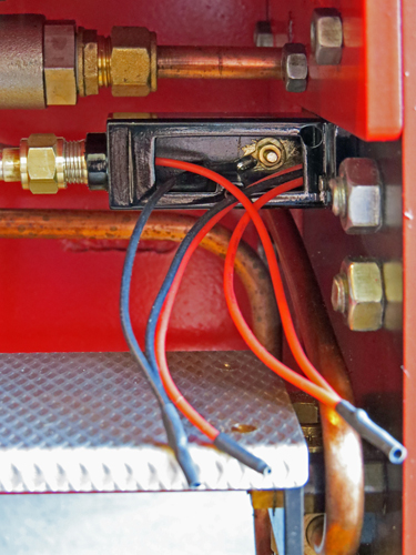 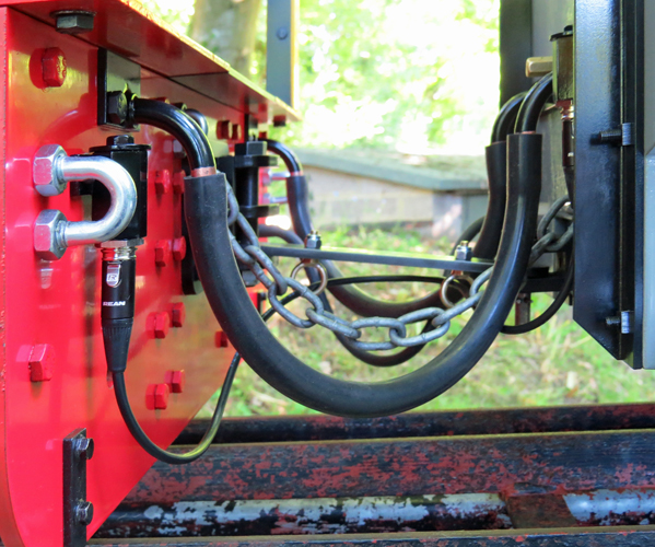 The
photo on the left shows the electrical junction box fitted to the
inside of the Feldbahn's rear buffer beam before the lid was bolted in
place and the photo on the right shows how the wiring is connected
between the engine and driving truck. The
photo on the left shows the electrical junction box fitted to the
inside of the Feldbahn's rear buffer beam before the lid was bolted in
place and the photo on the right shows how the wiring is connected
between the engine and driving truck.As mentioned previously the copper tubing that protects the silicone wire also provides the return electrical path so in effect the entire metal structure of the Feldbahn is the circuit "earth" in the same way that the metal body of your car provides the "earth" for all of your cars wiring. However the loose drawbar connection between the engine and driving truck should not be used as part of the wiring simply because it rattles about and could potentially create an intermittent electrical connection. For this reason an extra wire is used to make the return circuit connection between the engine and driving truck, and it is this wire that is joined to the engine's metalwork (and thus the copper wiring tubes) by the solder tag connection you can see inside the junction box. The photo on the right shows the complexities of connecting the Feldbahn to its driving truck. Already fitted were the two silicone rubber water pipes for the injector feeds, the silicone rubber pipe for the vacuum brakes, and the safety chain. The electrical connection for the headlamp uses latching connectors sold under the trade name "Tiny XLR" fitted to each end of the connecting cable. Brass fittings on the buffer beams house the sockets and the latching connectors are fitted to the three core cable which is routed through the rings fitted to the coupling bar. Routing the cable this way controls the slack needed to allow for the relative motion between the Feldbahn and driving truck while preventing the cable from dropping onto the track. The third core of the cable allows for any future addition such as cab lighting, although for the time being that feature is operated by a self contained battery and LED. |
|||
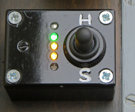  The
headlamp is controlled from the waterproof switch already fitted to the
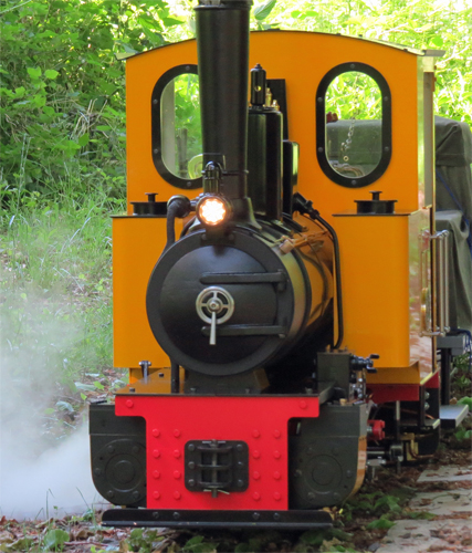
water level display mounted on the driving truck. In the
manner
of car systems the S position is dim (or side lights) while the H
position is bright (headlight). The photo on the right shows
the
lamp on its dim setting, and as a club member commented "when on bright
it is quite blinding to look at". Hopefully I'll be able to
see any
obstructions on the track when that night run comes around. The
headlamp is controlled from the waterproof switch already fitted to the
water level display mounted on the driving truck. In the
manner
of car systems the S position is dim (or side lights) while the H
position is bright (headlight). The photo on the right shows
the
lamp on its dim setting, and as a club member commented "when on bright
it is quite blinding to look at". Hopefully I'll be able to
see any
obstructions on the track when that night run comes around. |
|||
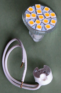 Experiments
showed that it would draw about 175mA from the
existing NiCad batteries fitted in my driving truck on full power
(which gave a very impressive light output) and that adding a 560 Ohm
series resistor would suitably reduce the light output for a
more pleasing effect. The lamp with its holder is shown in
the
photo on the right and as well as being the right diameter to fit
inside the headlamp body they were also just the right length.
An
evening using CAD then produced the
drawings for the lamp shown in the photo on the left.
Experiments
showed that it would draw about 175mA from the
existing NiCad batteries fitted in my driving truck on full power
(which gave a very impressive light output) and that adding a 560 Ohm
series resistor would suitably reduce the light output for a
more pleasing effect. The lamp with its holder is shown in
the
photo on the right and as well as being the right diameter to fit
inside the headlamp body they were also just the right length.
An
evening using CAD then produced the
drawings for the lamp shown in the photo on the left.