 |
 |
Modifying the Vacuum Braking
System
| What's Changed ? By mid 2013 the Vacuum Brake Valve fitted to the Stafford had changed significantly and the two types of valve are shown in the photo below with the original design on the left and the newer valve on the right. 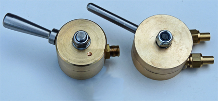 Apart
from the fact that the new valve is bigger the obvious difference is
that it has two pipe connections on its right hand side compared with
the one on the original valve that had been supplied with my Stafford.
If like me your Stafford had the
original valve I would really recommend changing to the newer type
because its performance is so much better, and later in this section I
will explain how I installed the new valve. However first I
will try explain why the new valve is so improved over the original. Apart
from the fact that the new valve is bigger the obvious difference is
that it has two pipe connections on its right hand side compared with
the one on the original valve that had been supplied with my Stafford.
If like me your Stafford had the
original valve I would really recommend changing to the newer type
because its performance is so much better, and later in this section I
will explain how I installed the new valve. However first I
will try explain why the new valve is so improved over the original.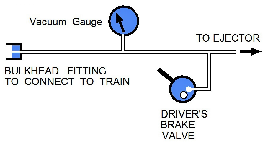 The
sketch on the right should help explain how the original Stafford
vacuum
brake system worked (you can read a lot more about vacuum brake system
operation by clicking here).
The single pipe connection on the brake
valve was effectively sealed when the brake valve was in the "Off"
position, but when the brake valve was moved to the "On" position a
small
hole through the valve cap became aligned with the single pipe
connection to let air into the Train Pipe. With the brake
valve
in the
"Off" position the valve's pipe connection was effectively closed so
the ejector could create a vacuum in the Train Pipe. When the
brakes were required the valve was effectively "opened" and air flowed
into the Train
Pipe destroying the vacuum and applying the brakes. For the
brakes to be fully "Off" or "On" was no problem, but to obtain a
partial
brake operation (to control a train descending a hill for example) was
very difficult. The driver had to try and find a valve
position
where the air leaking in through the valve cap hole exactly
counterbalanced the air being sucked out by the ejector.
Realistically the original Stafford vacuum brake system was
effectively a parking brake. The
sketch on the right should help explain how the original Stafford
vacuum
brake system worked (you can read a lot more about vacuum brake system
operation by clicking here).
The single pipe connection on the brake
valve was effectively sealed when the brake valve was in the "Off"
position, but when the brake valve was moved to the "On" position a
small
hole through the valve cap became aligned with the single pipe
connection to let air into the Train Pipe. With the brake
valve
in the
"Off" position the valve's pipe connection was effectively closed so
the ejector could create a vacuum in the Train Pipe. When the
brakes were required the valve was effectively "opened" and air flowed
into the Train
Pipe destroying the vacuum and applying the brakes. For the
brakes to be fully "Off" or "On" was no problem, but to obtain a
partial
brake operation (to control a train descending a hill for example) was
very difficult. The driver had to try and find a valve
position
where the air leaking in through the valve cap hole exactly
counterbalanced the air being sucked out by the ejector.
Realistically the original Stafford vacuum brake system was
effectively a parking brake.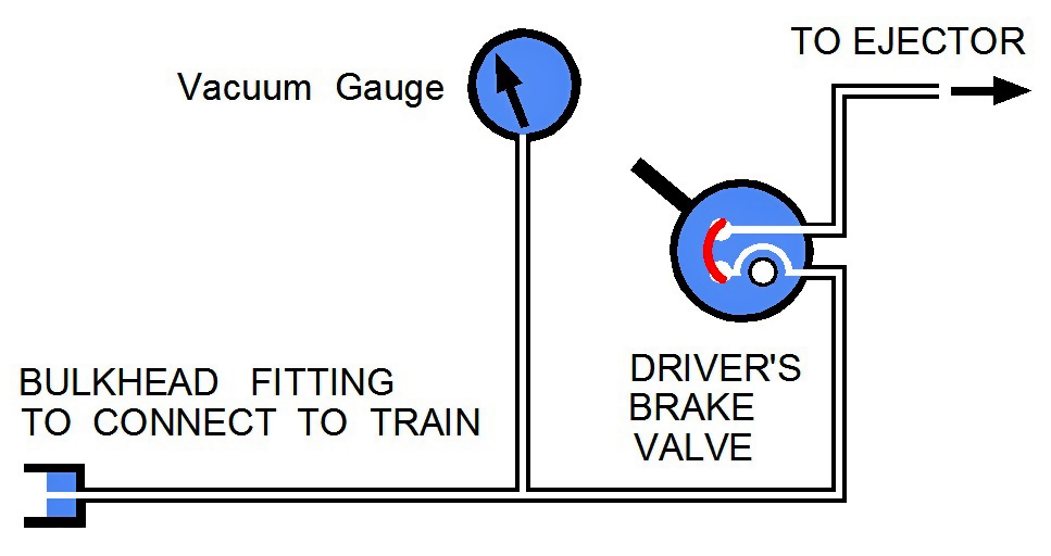 The
sketch on the left shows the revised vacuum braking system that results
from using the 2013 specification Vacuum Brake Valve. In this
new
valve the hole through the cap has been replaced by a groove, shown in
red in the sketch. Besides the two pipe connections the valve
body also has a very small hole (actually a shallow slot) that leads to
the open air. When the valve is in the "Off" position (as
shown
in
the sketch) the groove in the valve cap connects the two pipe
connections together and allows the ejector to create the vacuum in the
Train Pipe. As the valve is moved away from the "Off"
position
the
groove no longer links the two pipe connections, and the Train Pipe is
effectively sealed shut. Providing that you have no leaks in
the
system the Vacuum Gauge will not change from the value it showed when
the brake valve was in the "Off" position. Finally as the
valve
is
moved to the "On" position the groove connects the Train Pipe to the
small hole and allows air to flow into the Train Pipe destroying the
vacuum and applying the brakes. The critical difference from
the
original valve is that middle position where the Train Pipe is sealed
shut (this position is normally referred to as the "Lap" position).
If you want a partial brake application you no longer have to
perform an impossible juggling act with the brake valve, instead you
open the valve and when the desired level of braking is achieved you
move the brake lever back to the middle "Lap" position. If
you
look at the Vacuum Gauge it will be sitting at some intermediate value
and will not change (unless you have a leak in the brake system).
If you want to increase the braking you move the lever to the
"On"
position to let more air into the Train Pipe (reducing the vacuum
level) and then back to the "Lap" position. If you want less
braking you move the lever to the "Off" position to let the ejector
increase the vacuum level and then move the lever back to the "Lap"
position to hold the new level of braking. Full braking will
still
be achieved by leaving the lever in the "On" position; no braking is
achieved with the lever in the "Off" position. This new
system
offers the driver full and easy control of the train brakes rather than
the "all or nothing" that tended to result from the original
system. The
sketch on the left shows the revised vacuum braking system that results
from using the 2013 specification Vacuum Brake Valve. In this
new
valve the hole through the cap has been replaced by a groove, shown in
red in the sketch. Besides the two pipe connections the valve
body also has a very small hole (actually a shallow slot) that leads to
the open air. When the valve is in the "Off" position (as
shown
in
the sketch) the groove in the valve cap connects the two pipe
connections together and allows the ejector to create the vacuum in the
Train Pipe. As the valve is moved away from the "Off"
position
the
groove no longer links the two pipe connections, and the Train Pipe is
effectively sealed shut. Providing that you have no leaks in
the
system the Vacuum Gauge will not change from the value it showed when
the brake valve was in the "Off" position. Finally as the
valve
is
moved to the "On" position the groove connects the Train Pipe to the
small hole and allows air to flow into the Train Pipe destroying the
vacuum and applying the brakes. The critical difference from
the
original valve is that middle position where the Train Pipe is sealed
shut (this position is normally referred to as the "Lap" position).
If you want a partial brake application you no longer have to
perform an impossible juggling act with the brake valve, instead you
open the valve and when the desired level of braking is achieved you
move the brake lever back to the middle "Lap" position. If
you
look at the Vacuum Gauge it will be sitting at some intermediate value
and will not change (unless you have a leak in the brake system).
If you want to increase the braking you move the lever to the
"On"
position to let more air into the Train Pipe (reducing the vacuum
level) and then back to the "Lap" position. If you want less
braking you move the lever to the "Off" position to let the ejector
increase the vacuum level and then move the lever back to the "Lap"
position to hold the new level of braking. Full braking will
still
be achieved by leaving the lever in the "On" position; no braking is
achieved with the lever in the "Off" position. This new
system
offers the driver full and easy control of the train brakes rather than
the "all or nothing" that tended to result from the original
system. |
| Vacuum
Limiting Valve. Before describing how I fitted the new Brake Valve to my Stafford there is one other essential part of the vacuum braking system to discuss, the Vacuum Limiting Valve. At the time of writing this webpage this valve is not supplied by Station Road Steam, so if you want one you will have to source it yourself and then fit it. The photo below shows a vacuum limiting valve installed in my driving truck, but when I fitted the new style vacuum brake valve it had to be relocated to the Stafford's footplate for reasons explained later on this page. 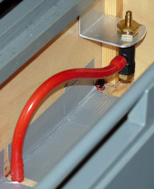 The purpose of a vacuum limiting valve is to set the maximum vacuum level that can be created in the train's braking system. Without a limiting valve it is possible to end up with the train brakes becoming stuck partially on as explained on the Operations / Driving page of this website, so to ensure that the Pinewood coach vacuum brakes operated satisfactorily I fitted a vacuum limiting valve into my driving truck. My valve was purchased from PNP Railways, but they are available from other suppliers or you can make one yourself. Silicone rubber vacuum tubing connected the valve to a "T" piece connector in the train brake pipe underneath the driving truck and the valve was simply attached using an aluminium bracket. The valve is supplied with a filter already fitted to prevent dirt from entering the system, so you only need to ensure that the filter entry will not become blocked by any loose objects. Once installed the valve needs to be adjusted. This is achieved by sealing off the train vacuum pipe at the train end of the driving truck and opening the Stafford's ejector steam valve a couple of turns. The limiting valve's adjuster is then rotated until the Stafford's vacuum gauge indicates 15 inches of Mercury, at which point the lock nut is tightened to prevent the valve's adjuster from moving any more. |
Retrofitting the New Style
Vacuum Brake Valve.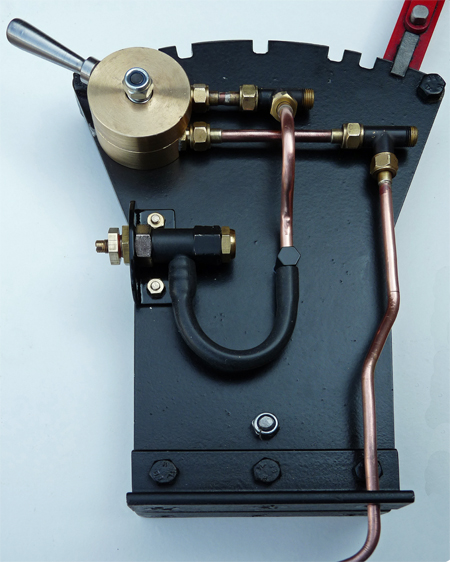 The
photo on the left shows the revised Vacuum Brake Valve installation of
my Stafford. The valve has been mounted in the same position
as
the original valve although it required two new countersunk holes to be
drilled through the reversing lever stand as the new valve is mounted
using two M4 screws (countersunk in my installation so as not to foul
the reversing lever). The pipe "T" connections from the
original
installation have been reused along with the two short lengths of
copper pipe, but most of the other pipes had to be replaced with new
ones. The
photo on the left shows the revised Vacuum Brake Valve installation of
my Stafford. The valve has been mounted in the same position
as
the original valve although it required two new countersunk holes to be
drilled through the reversing lever stand as the new valve is mounted
using two M4 screws (countersunk in my installation so as not to foul
the reversing lever). The pipe "T" connections from the
original
installation have been reused along with the two short lengths of
copper pipe, but most of the other pipes had to be replaced with new
ones.The lower of the two pipes connected to the new Vacuum Brake Valve connects to the original Train Pipe (the vertical pipe from the "T" connector) and via a new pipe to the Stafford's Vacuum Gauge. 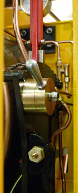 The upper of the two pipes connected to the new Vacuum Brake Valve connects to the Ejector via a new pipe, and to the Vacuum Limiting Valve via the "T" connection. The pipe leading to the Vacuum Limiting Valve has to cross over the Train Pipe so the pipe is quite tightly curved, and at its lower end it is retained in place by a small hexagonal block bolted to the reversing lever stand. A flexible silicon rubber vacuum pipe then connects to the vacuum limiting valve. The reason for connecting the Vacuum Limiting Valve between the Ejector and the Vacuum Brake Valve rather than in the Train Pipe (as in my original installation) is that the Vacuum Limiting Valve tends to leak slightly. If it was still connected to the Train Pipe it would be very hard to set and hold a vacuum level using the "Lap" position of the Vacuum Brake Valve. With the Vacuum Limiting Valve in this position it simply regulates the maximum vacuum level that the Ejector can create, but is always isolated from the Train Pipe as soon as the Vacuum Brake Lever is operated. Thankfully the Pinewood coaches have no leaks in their vacuum system, and a desired level of vacuum braking, once set, is maintained for several minutes without the driver needing to do anything. The photo on the right shows the reversing lever stand and the new vacuum braking components installed onto the footplate of my Stafford. |
Vacuum Steam Valve.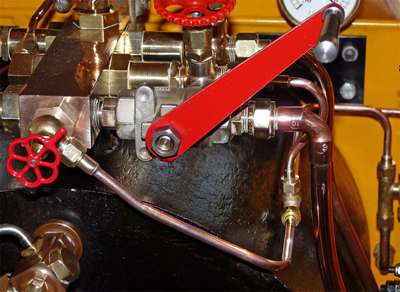 The
final vacuum braking system modification I made was to fit a secondary
steam
control valve to the ejector system. When using the vacuum
braking system I had been finding it difficult to adjust the steam
valve finely enough to set the flow necessary to maintain the vacuum
against the vacuum limiting valve. Using too much steam
doesn't
really matter but I decided to fit a second fine adjusting valve as
shown in the photo. The
final vacuum braking system modification I made was to fit a secondary
steam
control valve to the ejector system. When using the vacuum
braking system I had been finding it difficult to adjust the steam
valve finely enough to set the flow necessary to maintain the vacuum
against the vacuum limiting valve. Using too much steam
doesn't
really matter but I decided to fit a second fine adjusting valve as
shown in the photo.The 90 degree Globe Valve was fitted into the existing tapped hole in the end of the steam manifold (normally blanked off) and the outlet of the valve was connected into the original ejector steam pipe using a simple "T" piece connector. The globe valve was modified so that its normal 3/8"x32 input thread became 1/4" BSP to fit the manifold by turning off the original thread and then silver soldering the valve into a suitably made phosphor bronze 1/4" BSP bush. A new 1/4" BSP locking nut allows the valve to be fitted (using PTFE tape to ensure there are no steam leaks) with the outlet pointing in the desired direction. The valve shaft was also replaced with a new version made from Stainless Steel which had a longer needle valve to allow even finer control of the steam flow. 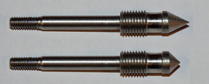 The photo on the left clearly
shows the lengthened section of the valve spindle. The photo on the left clearly
shows the lengthened section of the valve spindle.Trials have shown the new fine control valve to be very easy to use. To initially draw the vacuum in the train pipe and vacuum reservoirs the original ejector steam valve is used, but once the vacuum limiting valve is operating and the vacuum stable at 15 inches the original valve is fully closed and the fine control valve opened about 1/4 of a turn. This allows sufficient steam to flow through the ejector to maintain the vacuum, or the release the train brakes in about 3 seconds after they have been fully applied. Knowing the dimensions of the fine control valve I have worked out that this equates to a steam port area of 0.8 square millimetres being sufficient to operate the vacuum braking system, which would be just a 3 degree turn of a normal Stafford steam valve. I agree that the fine control is not really necessary, and this extra valve complicates things, but it works very nicely and I like it. Having easy fine control and not having to adjust the valves throughout an entire day of Public Running seems like a good feature to me. |
Filters.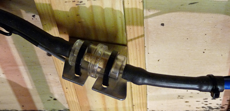 During the winter of 2012 - 2013
I
conducted an overhaul of the vacuum braking system fitted to the
coaches used at the Pinewood Miniature Railway and noticed that the
insides of the brake pipes were thickly covered in oily dirt.
Thankfully during the two years I had operated my Stafford
the vacuum
brakes had rarely been used (the coach brakes had been under
development) so the dirt had not been dragged into the locos system and
ejector, but to prevent any chance of that happening in the future I
decided to fit an air filter into the system. During the winter of 2012 - 2013
I
conducted an overhaul of the vacuum braking system fitted to the
coaches used at the Pinewood Miniature Railway and noticed that the
insides of the brake pipes were thickly covered in oily dirt.
Thankfully during the two years I had operated my Stafford
the vacuum
brakes had rarely been used (the coach brakes had been under
development) so the dirt had not been dragged into the locos system and
ejector, but to prevent any chance of that happening in the future I
decided to fit an air filter into the system.The first filter was inserted into the train pipe close to the rear train pipe connector of my driving truck as shown in the photo on the left. This is a cheap sintered bronze filter normally used for filtering fuel on garden machinery and was connected into the rigid plastic train pipe using 4mm bore silicon rubber vacuum tubing. Both items can easily be found on the Internet. |
Smoke Box.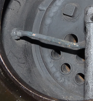 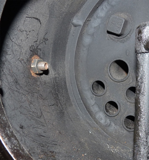 My
Stafford was one of the first three ever built and has many differences
to later locos. One of those was that the vacuum ejector
steam
was directed up the funnel in the smoke box in the same way as the
steam
blower. Having the ejector acting as a second steam blower is
not
ideal, so I removed the pipe inside the smoke box. The photos
are
self explanatory. My
Stafford was one of the first three ever built and has many differences
to later locos. One of those was that the vacuum ejector
steam
was directed up the funnel in the smoke box in the same way as the
steam
blower. Having the ejector acting as a second steam blower is
not
ideal, so I removed the pipe inside the smoke box. The photos
are
self explanatory.Note: All Stafford's currently being manufactured (Mid 2013) are not fitted with any ejector piping inside the smoke box. |
| Fitting Vacuum Brakes to my
Driving Truck |
This
section gives a very brief description of how my driving truck was
modified to incorporate vacuum braking and is included simply to show
how it can be done. As my driving truck is my own design the
installation will obviously have to be different on whatever driving
truck you use. If you don't understand the terms and
descriptions
used in the following paragraphs then I would recommend reading
Pinewood's Introduction to Vacuum Braking systems by clicking
here. The
photo on the left shows all of the major components of the vacuum
braking system of the driving truck, nearly all of which are sold by
PNP Railways. 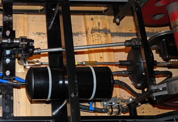 The large cylindrical object is the vacuum reservoir and the pipe from its right connects to the rear section of the vacuum brake cylinder. The pipe from its left connects to the driving trucks vacuum release valve. Just below the vacuum reservoir at its right hand end is the Train Pipe air filter. The pipe from its right goes to the Train Pipe connector on the rear of the driving truck, while the pipe from its left connects to both the Stafford locomotive and the vacuum brake cylinder via the blue "T" connector. The vacuum brake cylinder itself can be seen to the right of the vacuum reservoir (under the brake shoe cross beam). Its shafts have both been extended as there was no other way to fit it to my driving truck which was originally built without vacuum brakes. 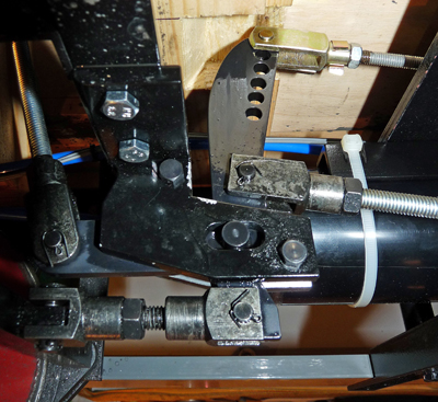 The
photo on the right shows the brake compensator linkage that forms the
crux of the braking system. The compensator allows the
braking
effort to be applied evenly to the wheels of both axles of the driving
truck by allowing the lever to slide in the slots of the lever mounting
brackets. The "gold" coloured clevis at the very top of the
photo
is operated by the vacuum brake cylinder. The "silver"
coloured
rod (vertical on the left) is the connection from the driving trucks
manual handbrake. The linkages to the two brake beams are
those
just above and below the slotted lever mounting bracket. The
photo on the right shows the brake compensator linkage that forms the
crux of the braking system. The compensator allows the
braking
effort to be applied evenly to the wheels of both axles of the driving
truck by allowing the lever to slide in the slots of the lever mounting
brackets. The "gold" coloured clevis at the very top of the
photo
is operated by the vacuum brake cylinder. The "silver"
coloured
rod (vertical on the left) is the connection from the driving trucks
manual handbrake. The linkages to the two brake beams are
those
just above and below the slotted lever mounting bracket.The only "trick" in designing the installation is to ensure that as much of the available vacuum brake cylinder motion as possible is used, and to still use the longest operating lever possible to create the maximum possible brake operating force. As the PNP Railways vacuum brake cylinder uses a rubber diaphragm its natural position is approximately midway along its travel, so PNP Railways recommend using a small spring or weight to "pull off" the brakes (e.g. move the diaphragm towards the brakes released end of its travel). On my driving truck the weight of the steel manual brake lever is sufficient to do that task. 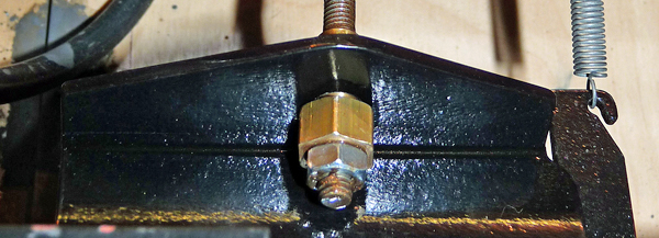 The
final part of the installation required is an adjuster / free motion
compensator which is shown in the photo on the left. As
explained
in the Pinewood Introduction to Vacuum Braking (see the link at the top
of this section) the PNP Railways Vacuum Brake Cylinder incorporates a
small spring loaded valve that opens when the Train Pipe vacuum pulls
the cylinder diaphragm to the fully "brakes released" position.
The braking system on my driving truck has a fixed mechanical
stop to define the brakes "Off" position, but the PNP Vacuum Brake
Cylinder is allowed to move beyond this position to open its internal
spring loaded valve (and thus create the vacuum in the reservoir).
The position at which this valve operates, and the actual
position of the brake linkages when the brakes are fully released thus
needs
to be accurately set, and I arranged this as follows: The
final part of the installation required is an adjuster / free motion
compensator which is shown in the photo on the left. As
explained
in the Pinewood Introduction to Vacuum Braking (see the link at the top
of this section) the PNP Railways Vacuum Brake Cylinder incorporates a
small spring loaded valve that opens when the Train Pipe vacuum pulls
the cylinder diaphragm to the fully "brakes released" position.
The braking system on my driving truck has a fixed mechanical
stop to define the brakes "Off" position, but the PNP Vacuum Brake
Cylinder is allowed to move beyond this position to open its internal
spring loaded valve (and thus create the vacuum in the reservoir).
The position at which this valve operates, and the actual
position of the brake linkages when the brakes are fully released thus
needs
to be accurately set, and I arranged this as follows:The threaded rod from the rear of the PNP Vacuum Brake Cylinder passes through a bracket attached to the driving truck chassis. The brass hexagon section seen in the photo screws onto the threaded rod, but it also has a smooth tubular extension that slides through the chassis bracket. I set the system up so that there is about 3mm of additional movement for the Vacuum Brake Cylinder past the point where the braking system is against the "Off" mechanical stop, and then use the lock nut against the brass hexagon to lock everything in place. Copper Slip lubricant is applied to the threaded rod, the brass hexagon, and the lock nut to ensure that the parts will not rust and seize up to allow future adjustments to be made. |