 |
 |
Building a Cab
| Having decided to
copy the style of cab
from the full size Bagnall 'Sir Tom' there was a lot of planning
to do before starting to cut any metal. For a start it was
obvious that if any imagined driver was going to fit between the end of
the cab side plates and the rear roof support struts then the footplate
would need extending rearwards. The width of the cab had to
be
carefully matched to that of the existing cab side plates, the front of
the cab had to line up with the proposed safety valve output pipe
extension, and most importantly the driver (me) had to be able to see
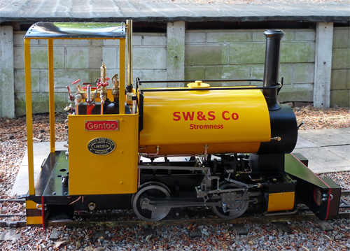
the pressure and vacuum gauges. The first step was to build a cab and roof from cardboard and to see how visible and accessible the controls and gauges were with it fitted to the loco. After a few adjustments I finally settled on a set of measurements, but even with the two gauges set as low as possible and on opposite sides of the cab (see Gauges and Safety Valve) the roof still had to be 2 inches (50mm) higher than I would have liked. The next step was to very carefully measure the dimensions of the existing cab parts and features, with special reference to the position of the safety valve outlet. These measurements were then used to create a CAD drawing of the cab end of the Stafford over which I could design the new cab and roof. The width of the cab was set at 1/4" (6mm) narrower than the internal width between the existing cab side plates so that a 1/8" (3mm) spacer strip could be fitted between the front cab struts and the existing cab sides to ensure that the new struts were clear of the existing cab side beading. The intended cab was to be fitted to the Stafford using three 2 BA bolts in each front strut through the existing cab side plates and a single M6 bolt each side passing through the footplate extension and screwing into blocks fitted inside the rear struts. The CAD package also predicted that the finished cab assembly, footplate extension, and steps would add 11 pounds (5 kgs) in weight and that all of this would be well behind the rear axle. So as to not unbalance the loco I decided that I wanted to add ballast to the front, which is why the front dumb buffers ended up being filled with lead ballast until they weighed almost 6 1/2 pounds (3 kgs) each. As you can see this cab conversion was a package of planned changes rather than an assortment of piecemeal additions. |
 Before
any other work commenced the first problem was to ensure that the
3/4"x3/4"x1/8" (20x20x3mm) mild steel angle could be shaped (or
created) for the two arched roof supports. A friend of mine
tried
to form angle using his track bender, but that not surprisingly
resulted in the angle bending in two planes. The radius for
the
roof was correct, but the roof would have been longer in the middle
than
at the edges. I then tried several local engineering
companies
(metal fabricators) but they all told me that what I wanted was
impossible. This seemed unlikely as there was plenty of angle
iron (much of it much thicker and wider) bent to similar radii on the
Mid Hants Railway where I work as a volunteer. Before
any other work commenced the first problem was to ensure that the
3/4"x3/4"x1/8" (20x20x3mm) mild steel angle could be shaped (or
created) for the two arched roof supports. A friend of mine
tried
to form angle using his track bender, but that not surprisingly
resulted in the angle bending in two planes. The radius for
the
roof was correct, but the roof would have been longer in the middle
than
at the edges. I then tried several local engineering
companies
(metal fabricators) but they all told me that what I wanted was
impossible. This seemed unlikely as there was plenty of angle
iron (much of it much thicker and wider) bent to similar radii on the
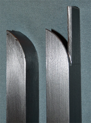
Mid Hants Railway where I work as a volunteer.Having failed to find a company who could roll the angle sections for me I considered fabricating the sections using a laser cut face and welding on a strip of metal to form the roof support. The problem was that I didn't think I could weld such an item without a lot of distortion, so I approached what I now consider to be my local equivalent of a blacksmith. This two man company undertakes all sorts of bespoke welding projects from gates, to vehicles and fuel tanks; and they had previously welded the aluminium body of the new lubricator that I had built for my Stafford. To my surprise they offered to roll some angle for me, and within a week I had two perfectly rolled lengths of angle that exactly met my requirements. Now the work on the cab could actually commence. |
 The first parts to make were
the four support struts from 3/4"x3/4"x1/8"
(20x20x3mm) mild steel angle. The front pair of struts are
35mm
shorter than the rear ones to clear the existing cab side mounting
angles and have three mounting holes drilled through their side faces,
while the rear struts had 5/8" (16mm) cubes of mild steel silver
soldered
inside the angle for the M6 mounting bolts to screw into.
As
shown in the photo the top of each strut was cut, bent, MIG welded and
dressed to create the start of the roof curve. A jig plate
was
then cut from an offcut of laminate faced furniture chipboard with its
width exactly that required to correctly space the struts across the
cab width. Once a strut was clamped to each side of the jig
(with
the bottom edges correctly aligned) the rolled angle was cut to fit
between the two struts. The rolled section and the two strut
top
curves were then drilled for the 4 BA "no slot" steel screws that would
eventually attach the roof sheet to the frame (the "no slot" screws
imitating round head rivets). After all the holes had been
drilled the rolled section was welded to the struts to create a cab
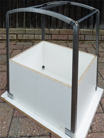
hoop. The procedure was then repeated for the other hoop. The first parts to make were
the four support struts from 3/4"x3/4"x1/8"
(20x20x3mm) mild steel angle. The front pair of struts are
35mm
shorter than the rear ones to clear the existing cab side mounting
angles and have three mounting holes drilled through their side faces,
while the rear struts had 5/8" (16mm) cubes of mild steel silver
soldered
inside the angle for the M6 mounting bolts to screw into.
As
shown in the photo the top of each strut was cut, bent, MIG welded and
dressed to create the start of the roof curve. A jig plate
was
then cut from an offcut of laminate faced furniture chipboard with its
width exactly that required to correctly space the struts across the
cab width. Once a strut was clamped to each side of the jig
(with
the bottom edges correctly aligned) the rolled angle was cut to fit
between the two struts. The rolled section and the two strut
top
curves were then drilled for the 4 BA "no slot" steel screws that would
eventually attach the roof sheet to the frame (the "no slot" screws
imitating round head rivets). After all the holes had been
drilled the rolled section was welded to the struts to create a cab
hoop. The procedure was then repeated for the other hoop. |
 Another
jig was then created to hold both hoops in their correct position so
that the longitudinal roof beams could be fitted. Each of the
three beams was made from 1/2"x1/2"x1/8" (12x12x3mm) mild steel angle
and also drilled for the 4BA "no slot" screws. Once MIG
welded in
place the two side beams were attacked with an angle grinder to give
them a correctly curved outer face to match the arch of the roof.
If you have read other pages of this website you may be
surprised
to see the mention of an angle grinder because I normally dress all my
welds with hand files and Wet & Dry paper because it gives me
more
control. The angle grinder is quite vicious and very
unforgiving
for model engineering, but it does have its uses for roughing out parts. Another
jig was then created to hold both hoops in their correct position so
that the longitudinal roof beams could be fitted. Each of the
three beams was made from 1/2"x1/2"x1/8" (12x12x3mm) mild steel angle
and also drilled for the 4BA "no slot" screws. Once MIG
welded in
place the two side beams were attacked with an angle grinder to give
them a correctly curved outer face to match the arch of the roof.
If you have read other pages of this website you may be
surprised
to see the mention of an angle grinder because I normally dress all my
welds with hand files and Wet & Dry paper because it gives me
more
control. The angle grinder is quite vicious and very
unforgiving
for model engineering, but it does have its uses for roughing out parts.If you look closely at the photo you will also see the two 4BA tapped holes in the front face of the roof arch that eventually attached the safety valve extension. Once the cab frame was removed from the jig it could at last be offered up to the Stafford to check that it would indeed fit, and to see what the finished cab would look like. All that remained was to make the roof skin and bolt it down, but that wasn't as easy as it sounds. Despite being told that aluminium has no place on model steam engines I decided to use 16 SWG aluminium for the roof simply because it would be soft enough for me to bend without any suitable metal forming tools. A sheet of cardboard was cut to fit the cab frame with an extra 1/4" (6mm) on each side to form the gutters. Having cut the aluminium to match the cardboard pattern, each side was clamped between two lengths of steel angle so that the gutter edges could be bent through 90 degrees using a hammer. The various hammer marks were then sanded out using Wet & Dry paper. The roof now had to be "rolled" to match the arch of the roof, with the outer ends forming ever decreasing radius curves. That isn't exactly easy to do, but eventually I managed it by hand bending the aluminium sheet over various bits of scrap tubing (actually water pipe and scaffold pole) and "forcing the bends" by compressing the curved sheet between my hands and the floor. For once the television had taught me something useful as I had previously watched similar techniques being used to form an aluminium car body in the series "American Hotrod". Once shaped the roof was clamped in place on the frame and all the holes drilled through for the mounting screws. |
 With
fabrication complete the frame and roof sheet were etch primed using
ACID 8 aerosols, and once dry the roof sheet was bolted in place.
More etch primer was then applied to paint all the
steel fixing bolts before the assembly was spray painted,
again
using aerosols. Rustoleum manufacture spray cans of all the
major
RAL colours, so it is quite easy to obtain aerosols of paint to
perfectly match the colour of any Stafford. As usual I used
Halfords gloss black for the outside of the roof. While
waiting a
week for the paint to harden I drilled the holes in existing cab side
panels to mount the front cab struts and spray painted the bolt heads
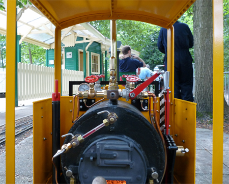
and 1/8" spacer strips. With
fabrication complete the frame and roof sheet were etch primed using
ACID 8 aerosols, and once dry the roof sheet was bolted in place.
More etch primer was then applied to paint all the
steel fixing bolts before the assembly was spray painted,
again
using aerosols. Rustoleum manufacture spray cans of all the
major
RAL colours, so it is quite easy to obtain aerosols of paint to
perfectly match the colour of any Stafford. As usual I used
Halfords gloss black for the outside of the roof. While
waiting a
week for the paint to harden I drilled the holes in existing cab side
panels to mount the front cab struts and spray painted the bolt heads
and 1/8" spacer strips.Throughout the manufacture of the cab, footplate extension, and the safety valve extension nothing had actually been bolted in place for a trial fit simply because I never had the time between runs to partially dismantle the loco (and because I didn't want unused holes in the model before the cab was complete). Thus I was very relieved when everything fitted into place without any fettling being required. The final photo shows the view through the cab while my Stafford 'Gentoo' is waiting for a Birthday Party event to start at my home "Pinewood" track. Although the drivers eye view is a lot higher than that of the photo the cab assembly does not in any way inhibit the drivers view of the controls and relocated gauges, nor do I find it to cause any problems when driving. As every comment has so far been very complimentary I am very pleased with the outcome of this package of modifications. However I do carry a copy of the 'Sir Tom' photo with me to satisfy those people who say that Bagnalls never had cabs or chevron painted dumb buffers. |